-
E-mail
2881930832@qq.com
-
Phone
18721098078
-
Address
2nd Floor, Building 2, No. 253 Yulu Road, Jiading District, Shanghai
Ankerui Electric Co., Ltd
Application and optimization of photovoltaic energy storage microgrid energy management system in substations!!!
Date: 2025-05-07Read: 19
Abstract: This article focuses on the application and optimization of photovoltaic energy storage systems in substations. Detailed explanation of the working principle of photovoltaic energy storage system and its important role in substations. Through the analysis of practical application cases, the problems and challenges of the system were explored, and targeted optimization strategies were proposed. The research results indicate that the rational application and optimization of photovoltaic energy storage systems can significantly improve the energy utilization efficiency and power supply stability of substations, providing strong support for the sustainable development of substations.
Keywords: photovoltaic energy storage system; Substation; application Optimization; Energy utilization efficiency; Power supply stability
0. Introduction
1. Application of photovoltaic energy storage system in substations
The introduction of photovoltaic energy storage systems in substations can effectively improve the stability and flexibility of the power system. The main access methods for photovoltaic energy storage systems are as follows:
(1) DC side connection
This method usually involves directly connecting the photovoltaic array and energy storage battery to the DC input of the inverter. The direct current generated by the photovoltaic array is converted into alternating current by an inverter and supplied to the substation, while the excess energy is stored in energy storage batteries. When the photovoltaic power is insufficient or the system fails, the energy storage battery releases electrical energy through the inverter to ensure the continuity of power supply.
(2) Communication side access
The communication side access methods are divided into transformer low-voltage side access and transformer high-voltage side access. Low voltage side access refers to connecting the energy storage system to the low voltage side of a transformer, sharing a transformer with the existing power grid; The high-voltage side connection is formed by the energy storage system forming an independent energy storage power station module, which is directly connected to the high-voltage power grid. This method facilitates the rapid scheduling and response of energy, and is suitable for substations with high requirements for power quality or large-scale energy storage.
(3) Hybrid access method
In some complex systems, a hybrid connection of DC and AC sides may be used. This can fully utilize the efficiency of the DC side and achieve more flexible energy scheduling and grid management through the AC side.
1.2 Application Example Analysis
Taking a 110kV substation in a certain region as an example, the substation has introduced a photovoltaic energy storage system. The system adopts a DC side access method and is equipped with a 1MW photovoltaic array and a 1.2MWh energy storage battery. The specific configuration is as follows:
Photovoltaic array: composed of multiple photovoltaic modules, installed on the roof of the substation and surrounding open spaces, fully utilizing solar energy resources.
Energy storage battery: using advanced lithium-ion battery packs, it has high energy density, long cycle life, and fast charging and discharging capabilities.
Inverter: Select grid connected inverters with high power point tracking (MPPT) function to ensure that photovoltaic modules are always in optimal working condition.
In practical operation, the photovoltaic energy storage system significantly improves the power supply reliability and economy of the substation. During the day, the electricity generated by photovoltaic arrays is prioritized for use in substations, and excess electricity is stored in energy storage batteries; At night or on rainy days, energy storage batteries release electricity to compensate for the shortage of photovoltaic power. The system can also automatically adjust the charging and discharging strategies of energy storage batteries according to changes in grid load, achieving optimized configuration of electrical energy.
1.3 Advantages and benefits brought by the application
(1) Improve power supply reliability
The photovoltaic energy storage system can quickly switch to islanding operation mode in case of grid failure or power outage, providing emergency power for substations and important loads, ensuring the continuity and reliability of power supply.
(2) Reduce operating costs
Photovoltaic energy storage systems utilize solar energy to generate electricity, reducing dependence on traditional energy sources and lowering electricity bills. At the same time, energy storage batteries are charged and discharged during peak and valley electricity price periods, achieving economic dispatch and further reducing operating costs.
(3) Improve power quality
Photovoltaic energy storage systems can smooth the fluctuations of photovoltaic grid connected power generation, improve the power factor and harmonic level of the power grid, and enhance the quality of electrical energy.
(4) Enhance the flexibility of the power grid
The introduction of energy storage systems enables the power grid to respond more flexibly to load changes, improve its regulation capabilities, and enhance its ability to respond to emergencies.
(5) Promote the utilization of renewable energy
The widespread application of photovoltaic energy storage systems has promoted the large-scale development and utilization of renewable energy such as solar energy, which helps to optimize the energy structure and achieve sustainable development.
2. Problems in the application of photovoltaic energy storage systems in substations
2.1 Technical limitations
The technical limitations in the application of photovoltaic energy storage systems in substations cannot be ignored. These restrictions mainly include
(1) Immature energy storage technology
Although significant progress has been made in energy storage technologies such as lithium-ion batteries, there is still room for improvement in terms of energy density, cycle life, and safety performance. The immaturity of energy storage technology may lead to low energy storage efficiency, shortened system lifespan, and safety hazards.
(2) Complex grid connection technology
The photovoltaic energy storage system needs to achieve bidirectional interaction with the power grid, which requires the system to have highly intelligent grid connected control technology. However, there are still some challenges in grid connected technology, such as how to predict photovoltaic output and how to quickly respond to grid dispatch instructions, which may affect the stable operation of the system.
(3) High difficulty in system integration
The photovoltaic energy storage system needs to be integrated with other equipment in the substation, such as transformers, switchgear, protective devices, etc. Due to possible technical differences and compatibility issues between different devices, system integration is difficult and requires a technical team to design and debug.
2.2 Cost and Investment Issues
The application of photovoltaic energy storage systems in substations still faces challenges in terms of cost and investment:
(1) High initial investment cost
The construction of photovoltaic energy storage systems requires a significant investment of funds, including the purchase costs of photovoltaic modules, energy storage batteries, inverters, control systems, and other equipment, as well as construction, installation, commissioning, and operation costs. The high initial investment cost is one of the important factors restricting the widespread application of photovoltaic energy storage systems.
(2) Long economic payback period
Although photovoltaic energy storage systems have significant energy conservation, emission reduction, and economic benefits, their high initial investment costs and relatively long economic payback period. This requires investors to have a long-term investment vision and financial strength, while also requiring corresponding policy support and subsidies from the government.
(3) Risk and Uncertainty
The investment in photovoltaic energy storage systems still faces certain risks and uncertainties, such as policy changes, equipment depreciation brought about by technological progress, and changes in market demand. These factors may all have an impact on investors' decisions and increase investment risks.
2.3 Management and Maintenance Challenges
(1) Shortage of operation and maintenance talents
Photovoltaic energy storage systems involve multiple technical fields and require operation and maintenance personnel to manage and maintain them. However, there is currently a relative shortage of talents with relevant skills and experience in the market, making it difficult to meet the growing market demand.
(2) Complex operation and maintenance management
The operation and maintenance management of photovoltaic energy storage systems is relatively complex, requiring regular inspections, maintenance, and troubleshooting of equipment. At the same time, real-time monitoring and analysis of the system's operational data are also required to promptly identify and resolve issues. The complexity of operation and maintenance management requires the operation and maintenance team to have a high sense of responsibility and skills.
(3) Difficulty in safety management
Photovoltaic energy storage systems involve hazardous factors such as high voltage electricity and flammable and explosive materials, making safety management difficult. The operation and maintenance team needs to strictly comply with safety operating procedures, conduct regular safety training and drills, and ensure the safe operation of the system. It is also necessary to establish sound safety management systems and emergency plans to cope with the occurrence of emergencies.
Optimization strategies for photovoltaic energy storage systems in substations
3.1 Technical improvement measures
With the increasing global demand for clean energy, the application of photovoltaic energy storage systems in substations is becoming increasingly widespread. In order to improve its performance and efficiency, a series of technological improvement measures are particularly important. In terms of photovoltaic modules, products with high stability should be selected. New photovoltaic materials and manufacturing processes can improve the efficiency of photovoltaic conversion and increase the power generation of the system. Optimize the layout and installation angle of photovoltaic modules to maximize the reception of solar radiation and improve energy harvesting efficiency. In the energy storage process, the use of advanced battery technology is key. For example, lithium-ion batteries have higher energy density and longer cycle life, which can better meet the energy storage needs of substations. By optimizing the Battery Management System (BMS), real-time monitoring of battery status is achieved, enabling charge and discharge control, prolonging battery life, and improving the reliability of energy storage systems. The performance of power conversion equipment also directly affects the efficiency of the entire photovoltaic energy storage system. Using inverters and chargers to reduce losses during energy conversion. Using intelligent control algorithms to regulate and optimize system power allocation, improving energy efficiency. In order to further enhance the stability and reliability of the system, monitoring and protection of the system should also be strengthened. Install advanced sensors and monitoring equipment, collect real-time system operation data, promptly detect and handle potential faults, and ensure the safe and stable operation of the system.
3.2 Cost Control and Investment Optimization Plan
Cost control and investment optimization are crucial considerations in the application of photovoltaic energy storage systems in substations. In terms of equipment procurement, more favorable prices can be obtained through large-scale centralized procurement. At the same time, establish long-term cooperative relationships with suppliers to ensure equipment quality while reducing procurement costs. Conduct thorough feasibility studies and cost-benefit analysis during the project planning and design phase. Reasonably plan the scale and configuration of the system to avoid overinvestment or underinvestment. Adopting standardized design schemes and modular equipment to reduce design and construction costs. Fully utilize government subsidy policies and preferential measures to reduce the initial investment cost of the project. Actively apply for renewable energy subsidies, tax incentives, etc., to improve the economic feasibility of the project. During the operation phase, optimize the system operation strategy to reduce operation and maintenance costs. For example, arranging the charging and discharging time of the energy storage system reasonably, fully utilizing the peak valley electricity price difference, and improving the economic benefits of the system. *Afterwards, pay attention to market trends and update and upgrade equipment in a timely manner to improve system performance and reduce long-term operating costs. By implementing reasonable cost control and investment optimization, the economic operation of photovoltaic energy storage systems in substations can be achieved.
3.3 Optimization methods for management and maintenance
Establish a sound management system, clarify the responsibilities of each department and personnel, standardize the operation process and maintenance standards of the system. Develop detailed operation and maintenance manuals to provide accurate guidance for operators. Strengthen the training of operation and maintenance personnel, improve their technical level and fault handling ability. Regularly organize training courses and technical exchange activities to familiarize operation and maintenance personnel with new technology and management requirements. Utilize information technology to achieve remote monitoring and management of the system. By installing intelligent monitoring devices and data collection systems, real-time system operation data can be obtained to achieve remote diagnosis and fault warning. This can promptly identify problems and take measures to reduce downtime caused by malfunctions. Develop a scientific and reasonable maintenance plan, regularly inspect, clean, and maintain photovoltaic modules, energy storage batteries, power conversion equipment, etc. For critical equipment, establish a preventive maintenance mechanism, replace vulnerable parts in advance, and reduce the probability of failure. Establish a spare parts management system to ensure timely replacement of required spare parts in case of equipment failure. Reasonably reserve commonly used spare parts and establish a rapid response mechanism with suppliers to ensure timely supply of spare parts.
Evaluation of the effectiveness of the optimized photovoltaic energy storage system in substations
The introduction and optimization of photovoltaic energy storage systems in substations have brought significant benefits in various aspects. The following is a detailed evaluation from three aspects: improving energy utilization efficiency, improving power supply stability, and economic and environmental benefits.
4.1 Evaluation of Energy Efficiency Improvement
The optimized photovoltaic energy storage system significantly improves energy utilization efficiency by adopting photovoltaic modules, intelligent energy storage integration technology, and collaborative control strategies. Specifically:
(1) Improvement of photovoltaic conversion efficiency
By selecting photovoltaic modules with high conversion efficiency, such as PERC and HJT, the efficiency of converting solar energy into electrical energy is greatly improved, reducing the loss of conversion from light energy to electrical energy.
(2) Efficiency optimization of energy storage system
Through advanced battery management systems and energy storage inverter technology, energy storage battery charging and discharging are achieved, reducing energy loss during the charging and discharging process and improving the overall efficiency of the energy storage system.
(3) Application of collaborative control strategy
The coordinated control of photovoltaic system and energy storage system dynamically adjusts the charging and discharging plan based on factors such as grid load, electricity price, and weather forecast, ensuring energy storage and release at the best time, further improving the energy utilization efficiency of the entire system.
4.2 Improvement of Power Supply Stability
The optimized photovoltaic energy storage system has a significant improvement effect on power supply stability in substations. When photovoltaic power generation fluctuates due to natural factors such as weather, the energy storage system can quickly respond, release stored electricity, compensate for the shortcomings of photovoltaic power generation, and maintain stable power output. Through advanced monitoring and control systems, real-time monitoring of load changes and power quality parameters in the power grid, timely adjustment of the working status of the photovoltaic energy storage system, ensuring stable output voltage and frequency, effectively reducing voltage fluctuations and frequency deviations. In addition, the optimized system has stronger fault response capabilities. In the event of a power grid failure or emergency, the energy storage system can serve as a backup power source, providing continuous power support for key equipment and loads, ensuring the normal operation of the substation, and improving the reliability and continuity of power supply. Monitoring and evaluating various indicators of power supply stability, such as voltage fluctuation range, power outage time, etc., the results show that the optimized photovoltaic energy storage system significantly improves the power supply stability of the substation and provides users with more reliable power services.
4.3 Economic and Environmental Benefit Analysis
The optimized photovoltaic energy storage system has brought significant economic and environmental benefits in substations. From an economic perspective, on the one hand, the improved energy utilization efficiency and stable power supply capacity have reduced the operating costs of substations. Reduced equipment damage and maintenance costs caused by power quality issues, while reducing reliance on traditional energy sources and saving energy procurement costs. On the other hand, by making reasonable use of the peak valley electricity price difference, the energy storage system charges during low electricity prices and discharges during high electricity prices, bringing additional economic benefits to the substation. In terms of environmental benefits, the application of photovoltaic energy storage systems greatly reduces the consumption of traditional fossil fuels, thereby significantly reducing greenhouse gas emissions and pollutant emissions. It is of great significance to reduce the impact of climate change and improve the quality of the local ecological environment. With the continuous advancement of technology and the gradual reduction of costs, the initial investment cost of photovoltaic energy storage systems is also gradually decreasing, further improving their economic feasibility. The environmental benefits it brings have also made positive contributions to the sustainable development of society.
5 Acrel-2000MG Microgrid Energy Management System
5.1 Overview
Acrel-2000MG microgrid energy management system is a specially developed enterprise microgrid energy management system by our company based on the requirements of microgrid monitoring system and microgrid energy management system under the new power system, summarizing the advanced experience of research and production at home and abroad. This system is designed to connect photovoltaic systems, wind power generation, energy storage systems, and charging stations. It can collect and analyze data 24/7, directly monitor the operation status and health of photovoltaic, wind power, energy storage systems, and charging stations. It is a management system that integrates monitoring and energy management. The system aims to optimize economic operation on the basis of safety and stability, promote the application of renewable energy, improve the stability of power grid operation, and compensate for load fluctuations; Effectively achieve demand management on the user side, eliminate day night peak valley differences, smooth loads, improve the operational efficiency of power equipment, and reduce power supply costs. Providing a new solution for safe, reliable, and economical operation of enterprise microgrid energy management.
The microgrid energy management system should adopt a hierarchical distributed structure, and the entire energy management system is physically divided into three layers: device layer, network communication layer, and station control layer. The station level communication network adopts standard Ethernet and TCP/IP communication protocols, and physical media can include fiber optic cables, network cables, shielded twisted pair cables, etc. system support ModbusRTU、ModbusTCP、CDT、IEC60870-5-101、IEC60870-5-103、IEC60870-5-104、MQTT Waiting for communication protocols.
5.2 Technical Standards
The national standards followed in this plan are:
The equipment provided in this technical specification shall comply with the following regulations, laws, and industry standards:
GB/T26802.1-2011 General Specification for Industrial Control Computer Systems Part: General Requirements
GB/T26806.2-2011 Industrial Control Computer Systems - Basic Platform for Industrial Control Computers - Part 2: Performance Evaluation Methods
GB/T26802.5-2011 General Specification for Industrial Control Computer Systems Part 5: Site Safety Requirements
GB/T26802.6-2011 General Specification for Industrial Control Computer Systems Part 6: Acceptance Outline
GB/T2887-2011 General Specification for Computer Sites
GB/T20270-2006 Information Security Technology - Network Basic Security Technical Requirements
GB50174-2018 Design Specification for Electronic Information System Room
DL/T634.5101 Remote Control Equipment and Systems Part 5-101: Transmission Protocol Basic Remote Control Task Supporting Standards
DL/T634.5104 Remote control equipment and systems - Part 5-104: Transmission protocol using standard transmission protocol subset IEC60870-5-Network access 101
GB/T33589-2017 Technical Regulations for Microgrid Access to Power Systems
GB/T36274-2018 Technical Specification for Microgrid Energy Management System
GB/T51341-2018 Microgrid Engineering Design Standards
GB/T36270-2018 Technical Specification for Microgrid Monitoring System
DL/T1864-2018 Technical Specification for Independent Microgrid Monitoring System
T/CEC182-2018 Microgrid Grid Connection Dispatch Operation Specification
T/CEC150-2018 Technical Specification for Low Voltage Microgrid Grid Integration Device
T/CEC151-2018 Technical Specification for Operation and Control of Grid connected AC/DC Hybrid Microgrid
T/CEC152-2018 Technical Requirements for Demand Response of Grid connected Microgrids
T/CEC153-2018 Technical Guidelines for Load Management of Grid connected Microgrids
T/CEC182-2018 Microgrid Grid Connection Dispatch Operation Specification
T/CEC5005-2018 Design Specification for Microgrid Engineering
NB/T10148-2019 Microgrid Part: Guidelines for Microgrid Planning and Design
NB/T10149-2019 Microgrid Part: Guidelines for Microgrid Operation
5.3 Applicable occasions
The system can be applied to renewable energy system monitoring and energy management needs in cities, highways, industrial parks, commercial and industrial areas, residential areas, smart buildings, islands, and areas without electricity.
5.4 Model Description

5.5 System Configuration
5.5.1 System Architecture
This platform is designed with a layered and distributed structure, including the station control layer, network layer, and device layer. The detailed topology structure is as follows:

Figure 1 Typical Networking Mode of Microgrid Energy Management System
5.6 System Functions
5.6.1 Real time monitoring
The human-machine interface of the microgrid energy management system should be user-friendly, and it should be able to visually display the operating status of each electrical circuit in the form of a system electrical diagram. Real time monitoring of electrical parameters such as voltage, current, power, and power factor of each circuit should be carried out, and the closing and opening status of circuit breakers, isolating switches, and related fault, alarm, and other signals of each circuit should be dynamically monitored. Among them, the electrical parameters of each subsystem circuit mainly include: three-phase current, three-phase voltage, total active power, total reactive power, total power factor, frequency, and cumulative positive active energy; The main state parameters include switch status, circuit breaker fault tripping alarm, etc.
The system should be able to manage the power generation of distributed power sources and energy storage systems, allowing management personnel to real-time grasp the output information, revenue information, energy storage charging status of power generation units, as well as the operating power settings of power generation units and energy storage units.
The system should be able to manage the status of the energy storage system, provide timely alarms based on the state of charge of the energy storage system, and support regular battery maintenance.
The monitoring system interface of the microgrid energy management system includes the system main interface, which includes the microgrid photovoltaic, wind power, energy storage, charging piles, and overall load composition, including revenue information, weather information, energy conservation and emission reduction information, power information, electricity quantity information, voltage and current situation, etc. According to different needs, charging, energy storage, and photovoltaic system information can also be displayed.
Figure 2 System main interface
The sub interface mainly includes the system main wiring diagram, photovoltaic information, wind power information, energy storage information, charging station information, communication status, and some statistical lists.
5.6.1.1 Photovoltaic Interface


Figure 3 Photovoltaic System Interface
This interface is used to display information about the photovoltaic system, mainly including monitoring and alarm of the DC and AC operating status of the inverter, statistics and analysis of the power generation of the inverter and the power station, monitoring and analysis of the power generation of the grid connected cabinet, statistics of the annual effective utilization hours of the power station, statistics of power generation income, carbon emission reduction statistics, monitoring of irradiance/wind power/environmental temperature and humidity, simulation and efficiency analysis of power generation; Simultaneously display the total power, voltage and current of the system, as well as the operational data of each inverter.
5.6.1.2 Energy Storage Interface

Figure 4 Energy storage system interface
This interface is mainly used to display the energy storage installed capacity, current charging and discharging capacity, revenue, SOC change curve, and electricity change curve of this system.

Figure 5 PCS parameter setting interface for energy storage system
This interface is mainly used to display the settings of PCS parameters, including power on/off, operating mode, power settings, and voltage and current limits.

Figure 6 BMS parameter setting interface for energy storage system
This interface is used to display the settings of BMS parameters, mainly including cell voltage, temperature protection limit, battery pack voltage, current, temperature limit, etc.

Figure 7 PCS grid side data interface of energy storage system
This interface is used to display PCS grid side data, mainly including phase voltage, current, power, frequency, power factor, etc.

Figure 8: PCS AC side data interface of energy storage system
This interface is used to display data on the AC side of PCS, mainly including phase voltage, current, power, frequency, power factor, temperature values, etc. Simultaneously issue alerts for abnormal information on the communication side.

Figure 9: Data Interface of PCS DC Side in Energy Storage System
This interface is used to display data on the DC side of PCS, mainly including voltage, current, power, electricity, etc. Simultaneously issue an alarm for abnormal information on the DC side.

Figure 10 Energy Storage System PCS Status Interface
This interface is used to display PCS status information, mainly including communication status, operating status, STS operating status, and STS fault alarms.

Figure 11 Energy Storage Battery Status Interface
This interface is used to display BMS status information, mainly including the operating status of the energy storage battery, system information, data information, and alarm information, while also displaying the current SOC information of the energy storage battery.

Figure 12 Energy storage battery cluster operation data interface
This interface is used to display information about battery clusters, mainly including the cell voltage and temperature of each energy storage module, and to display the current cell's Z-high and Z-low voltage, temperature values, and corresponding positions.
5.6.1.3 Wind Power Interface


Figure 13 Wind Power System Interface
This interface is used to display information about the wind power system, mainly including monitoring and alarm of the operation status of the DC and AC sides of the inverter control integrated machine, statistics and analysis of the power generation of the inverter and the power station, statistics of the annual effective utilization hours of the power station's power generation, statistics of power generation income, carbon reduction statistics, monitoring of wind speed/wind speed/environmental temperature and humidity, simulation of power generation and efficiency analysis; Simultaneously display the total power, voltage and current of the system, as well as the operational data of each inverter.
5.6.1.4 Charging Station Interface


Figure 14 Charging Station Interface
This interface is used to display information about the charging station system, mainly including the total power consumption of charging stations, the power and electricity consumption of AC and DC charging stations, electricity costs, change curves, and operational data of each charging station.
5.6.1.5 Video Monitoring Interface

Figure 15 Microgrid Video Monitoring Interface
This interface mainly displays the video images connected to the system, and achieves preview, playback, management, and control through different configurations.
5.6.1.6 Power generation forecast
 The system should be able to predict the short-term and ultra short term power generation of distributed power generation through historical power generation data, measured data, and future weather forecast data, and display the qualification rate and error analysis. According to power prediction, manual input or automatic generation of power generation plans can be carried out, which facilitates users to centrally control the new energy generation of the system.
Figure 16 Photovoltaic prediction interface
5.6.1.7 Strategy Configuration
The system should be able to set the system operation mode and configure different control strategies based on power generation data, energy storage system capacity, load demand, and time of use electricity price information. Such as peak shaving and valley filling, cycle planning, demand control, orderly charging, dynamic expansion, etc.


Figure 17 Strategy Configuration Interface
5.6.2 Running Reports
It should be possible to query the operating parameters of each subsystem, circuit, or equipment at a fixed time. The electrical parameter information displayed in the report should include: phase current, three-phase voltage, total power factor, total active power, total reactive power, positive active energy, etc.

Figure 18 Running Report
5.6.3 Real time alarm
It should have real-time alarm function, and the system should be able to remotely signal the starting and closing of inverters and bidirectional converters in each subsystem, as well as issue alarms when internal protection actions or accident trips occur. It should be able to display alarm events or trip events in real time, including the name of the protection event and the time of the protection action; And it should be able to notify relevant personnel in the form of pop ups, sounds, text messages, and phone calls.

Figure 19 Real time alarm
5.6.4 Historical Event Query
It should be able to store and manage records of remote signal displacement, protection actions, accident tripping, as well as events such as voltage, current, power, power factor, cell temperature (lithium-ion batteries), pressure (flow batteries), light, wind speed, and air pressure exceeding limits, making it convenient for users to trace the history of system events and alarms, query statistics, and analyze accidents.

Figure 20 Historical event query
5.6.5 Power Quality Monitoring
It should be possible to continuously monitor the power quality of the entire microgrid system, including steady-state and transient states, so that management personnel can grasp the power quality situation of the power supply system in real time, in order to timely detect and eliminate power supply instability factors.
1) The main interface of the power supply system should be able to display in real time the communication status of the monitoring devices at each power quality monitoring point, the total distortion rate of the A/B/C phase voltages at each monitoring point, the three-phase voltage imbalance B points B and positive/negative/zero sequence voltage values, and the three-phase current imbalance B points B and positive/negative/zero sequence current values;
2) Harmonic analysis function: The system should be able to display in real-time the total harmonic distortion rate of A/B/C three-phase voltage, A/B/C three-phase current, odd harmonic voltage, odd harmonic current, even harmonic voltage, and even harmonic current; It should be able to display the 2-63rd harmonic voltage content, 2-63rd harmonic voltage content, 0.5-63.5th harmonic voltage content, and 0.5-63.5th harmonic current content in a bar chart;
3) Voltage fluctuation and flicker: The system should be able to display the fluctuation values of A/B/C three-phase voltage, short flicker values of A/B/C three-phase voltage, and long flicker values of A/B/C three-phase voltage; Should be able to provide A/B/C three-phase voltage fluctuation curves, short flicker curves, and long flicker curves; Should be able to display voltage deviation and frequency deviation;
4) Power and energy metering: The system should be able to display the active power, reactive power, and apparent power of A/B/C three-phase systems; It should be able to display the total active power, total reactive power, total apparent power, and total power factor of the three-phase system; Should be able to provide active load curves, including daily active load curves (folded) and annual active load curves (folded);
5) Voltage transient monitoring: In the event of power quality transient events such as voltage rise, voltage drop, or short-term interruption, the system should be able to generate alarms and notify relevant personnel in the form of pop ups, flashes, sounds, text messages, phone calls, etc; The system should be able to view the waveforms before and after the occurrence of corresponding transient events.
6) Power quality data statistics: The system should be able to display statistical data stored for 1 minute and 2 hours, including mean, Z-large value, Z-small value, 95% probability value, and root mean square value.
7) Event record viewing function: Event records should include event name, status (action or return), waveform number, out of limit value, fault duration, and time of event occurrence.

Figure 21 Power Quality Interface of Microgrid System
5.6.6 Remote Control Function
It should be possible to remotely control devices throughout the entire microgrid system. System maintenance personnel can complete remote control operations through the main interface of the management system, and follow the operation sequence of remote control preset, remote control return to school, and remote control execution. They can promptly execute the corresponding operation commands of the scheduling system or the station.

Figure 22 Remote Control Function
5.6.7 Curve Query
It should be possible to directly view various electrical parameter curves on the curve query interface, including three-phase current, three-phase voltage, active power, reactive power, power factor, etc SOC、SOH、 Curve of changes in charge and discharge capacity.

5.6.8 Statistical Reports
With the function of timed meter reading and summary statistics, users can freely query the electricity consumption of each distribution node at any time period since the normal operation of the system, that is, the statistical analysis report of the incoming power consumption of the node and the power consumption of each branch circuit. [6] Statistical analysis of energy exchange between microgrids and external systems; Analysis of energy efficiency, benefits, and other aspects of system operation; Capable of analyzing the reliability of microgrid power supply, including annual power outage time, annual power outage frequency, etc; Capable of conducting power quality analysis on the grid connection points of grid connected microgrids.
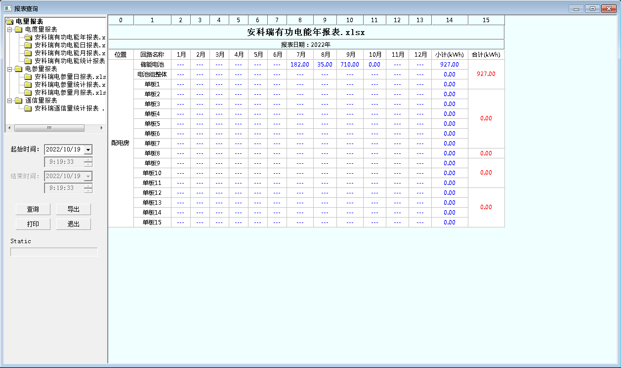
Figure 24 Statistical Report
5.6.8.1 Network Topology Diagram
The system supports real-time monitoring of the communication status of various devices connected to the system, and can fully display the entire system network structure; It can diagnose the communication status of equipment online, and automatically display the faulty equipment or component and its faulty location on the interface when network abnormalities occur.
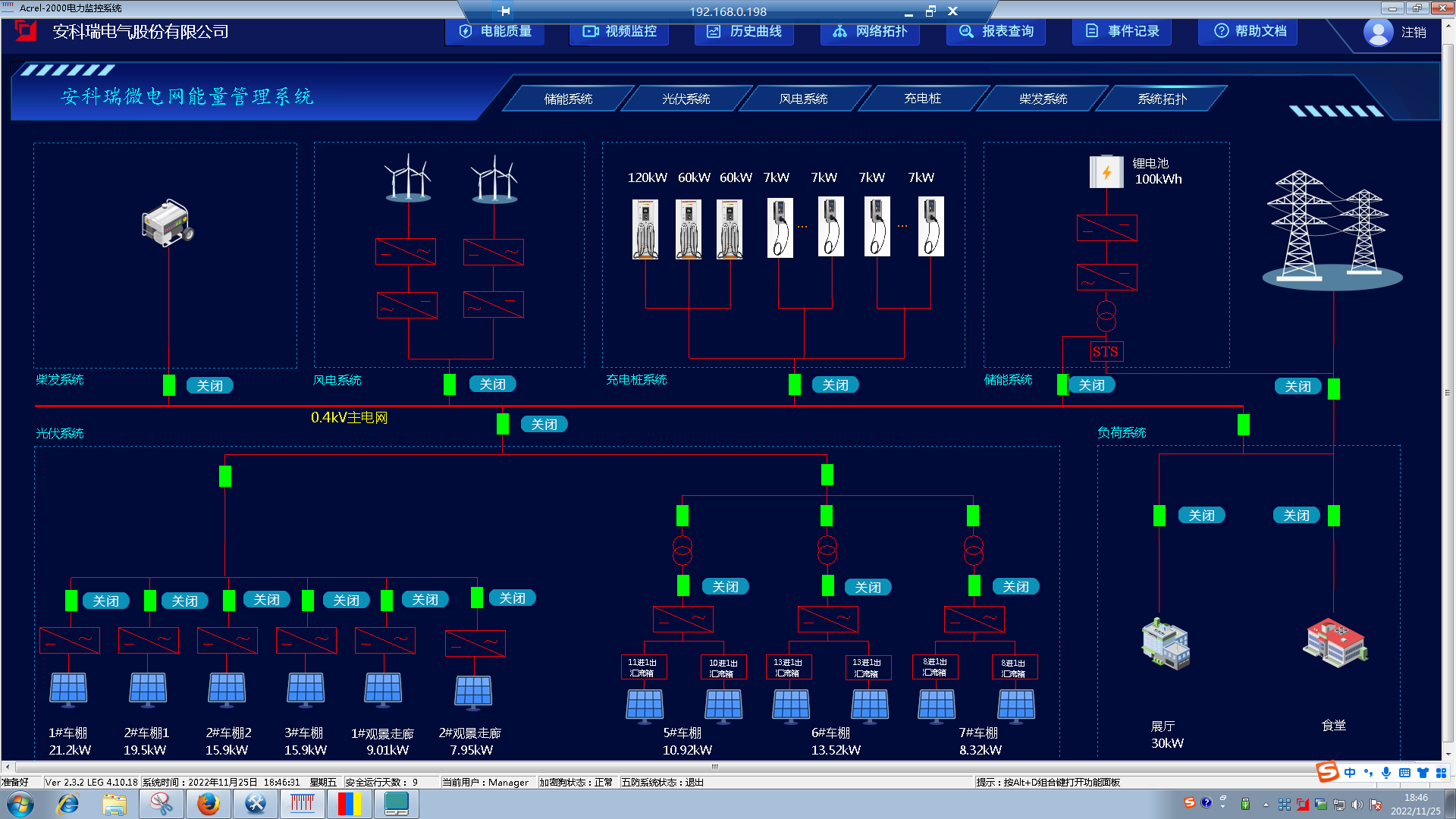
Figure 25 Topology interface of microgrid system
This interface mainly displays the topology of microgrid systems, including the composition of the system, grid connection methods, circuit breakers, meters, and other information. 5.6.8.2 Communication Management
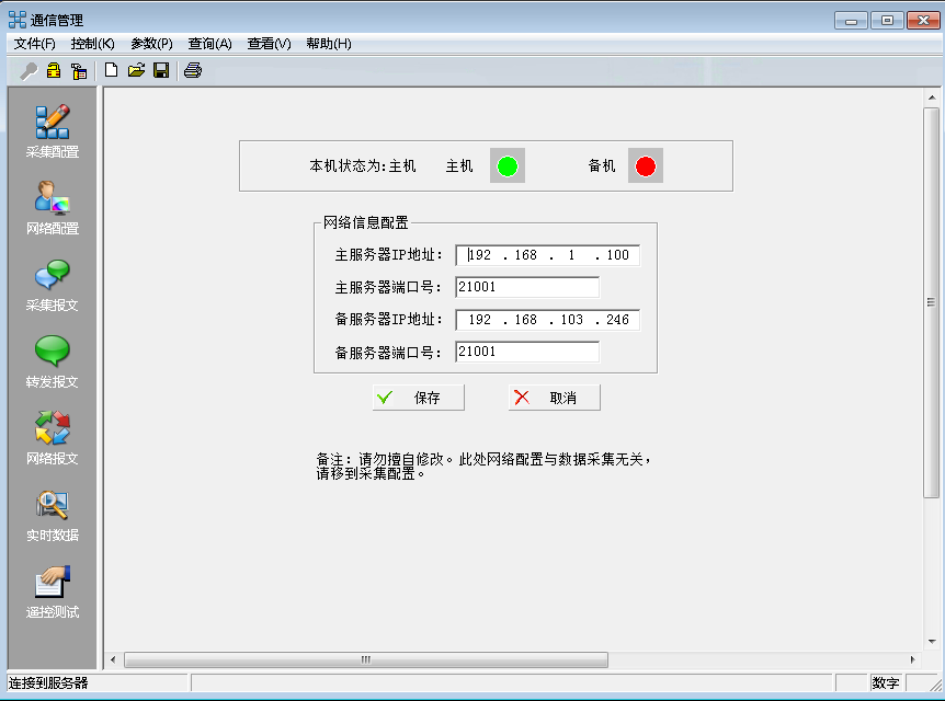
It can manage, control, and monitor the real-time communication status of devices within the entire microgrid system. System maintenance personnel can right-click on the main program of the management system to open the communication management program [6], and then select communication control to start all ports or a certain port, quickly viewing the communication and data status of a certain device. Communication should support ModbusRTU、ModbusTCP、CDT、IEC60870-5-101、IEC60870-5-103、IEC60870-5-104、MQTT Waiting for communication protocols.
5.6.8.3 User Permission Management
Should have the function of setting user permission management. [5] User permission management can prevent unauthorized operations (such as remote control, parameter modification, etc.). It is possible to define login names, passwords, and operational permissions for users of different levels, providing reliable security for system operation, maintenance, and management.

5.6.8.4 Fault Recording
It should be possible to automatically and accurately record the changes in various related electrical quantities before and after a system failure. By analyzing and comparing these electrical quantities, it plays an important role in analyzing and handling accidents, determining whether protection is operating correctly, and improving the safe operation level of the power system. Among them, a total of 16 fault waveforms can be recorded, [6] each waveform can trigger 6 segments of waveform recording, and each waveform recording can record the waveform of the first 8 cycles before the fault and the last 4 cycles after the fault, with a total recording time of 46 seconds. Each sampling point recording includes at least 12 analog waveforms and 10 switch waveforms.

5.6.8.5 Accident Remembrance
It can automatically record all real-time scanning data before and after the accident, including switch position, protection action status, remote measurement, etc., forming the data basis for accident analysis.
Users can customize the initiation event for accident recall, and when each event occurs, store relevant point data for the accident scan cycle and 10 scan cycles after the accident. The data points for initiating events and monitoring can be determined and modified at will by user Z.

Figure 29 Accident Remembrance
6 Hardware and its supporting products
| serial number | equipment | model | picture | explanation |
| 1 | energy management system | Acrel-2000MG |
| The data collection and monitoring of internal equipment consists of a communication management machine, industrial tablet computer, serial server, remote signaling module, and related communication accessories. Data collection, uploading, and forwarding to servers and collaborative control devices Strategic control: planning curve, demand control, peak shaving and valley filling, backup power supply, etc |
| 2 | Monitor | 25.1-inch LCD display |
| System software display carrier |
| 3 | UPS power supply | UPS2000-A-2-KTTS |
| Provide backup power for the monitoring host |
| 4 | printer | HP108AA4 |
| Used to print operation records, parameter modification records, parameter exceeding and exceeding limits, system accidents, equipment failures, protection operation records, etc., with call printing as the main method |
| 5 | Speaker | R19U |
| Play alarm event information |
| 6 | Industrial network switch | D-LINKDES-1016A16 |
| Providing 16 port 100Mbps industrial network switches solves technical issues such as real-time communication, network security, intrinsic safety, and explosion-proof technology |
| 7 | GPS clock | ATS1200GB |
| Using GPS to synchronize satellite signals, receive 1pps and serial time information, and synchronize the local clock with the time on the GPS satellite |
| 8 | Exchange metering meters | AMC96L-E4/KC |
| Measurement of electrical parameters (such as single-phase or three-phase current, voltage, active power, reactive power, apparent power, frequency, power factor, etc.), multi rate energy metering, four quadrant energy metering, harmonic analysis, and energy monitoring and assessment management. Multiple peripheral interface functions: equipped with RS485/MODBUS-RTU protocol: with switch input and relay output, it can achieve the functions of 'relay' and 'remote control' of circuit breaker switches |
| 9 | DC metering meter | PZ96L-DE |
| It can measure voltage, current, power, forward and reverse electrical energy in DC systems. Can be equipped with RS485 communication interface, analog data conversion, switch input/output and other functions |
| 10 | Power quality monitoring | APView500 |
| Real time monitoring of power quality such as voltage deviation, frequency dip, three-phase voltage imbalance, voltage fluctuations and flicker, and disturbances, recording various power quality events, and locating disturbance sources. |
| 11 | Anti islanding device | AM5SE-IS |
| Anti islanding protection device, which disconnects from the external power grid after a power outage |
| 12 | Box transformer measurement and control device | AM6-PWC |
| Develop integrated protection, measurement and control, and communication devices for photovoltaic, wind energy, and energy storage boost transformers with different requirements, including protection, communication management, and ring network switch functions |
| 13 | Communication management machine | ANet-2E851 |
| Capable of summarizing data sets for devices such as water meters, gas meters, electricity meters, and microcomputer protection terminals according to different collection rules: It provides multiple functions such as protocol conversion, transparent forwarding, data encryption and compression, data conversion, edge computing, etc.: real-time multitask parallel processing of data acquisition and data forwarding, which can deliver data to the platform via multiple links: |
| 14 | serial port server | Aport |
| Function: Convert the status data of the 'auxiliary system' and provide feedback to the energy management system. 1) Air conditioning switch, temperature control, and power-off (achieved through secondary switch) 2) Upload various air switch signals of the distribution cabinet 3) Upload UPS internal power information, etc 4) Connect to devices such as electricity meters and BSMU |
| 15 | Remote signaling module | ARTU-K16 |
| 1) Feedback the status of each device and send relevant data to the serial server: Read the fire VO signal and forward it to the upper layer (shutdown, event reporting, etc.) 2) Collect water immersion sensor information and forward it to the upper layer (water immersion signal event reporting) 4) Read the sensor information of the access control process and forward it |


