-
E-mail
2881930832@qq.com
-
Phone
18721098078
-
Address
2nd Floor, Building 2, No. 253 Yulu Road, Jiading District, Shanghai
Ankerui Electric Co., Ltd
Implementation and Application Plan of Integrated Automation System for Large Industrial Enterprise Substation
Date: 2025-05-08Read: 17
Summary:This article focuses on the design and operation optimization of substations in large industrial enterprises. By analyzing the characteristics and functions of large industrial enterprise substations, key aspects such as substation site selection, equipment selection, and automation system design were discussed. At the same time, in-depth analysis was conducted on the operation management mode, maintenance strategy, and energy efficiency optimization methods of the substation. Research has shown that scientifically reasonable substation design and operation optimization can significantly improve power supply reliability, reduce operating costs, and provide strong guarantees for the stable operation of large industrial enterprises. This study provides theoretical guidance and practical reference for the planning, construction, and operation management of substations in large industrial enterprises.
keywordLarge industrial enterprises; Substation design; Operational optimization; Automation system; energy efficiency management
0 Introduction
With the rapid development of industrial production, large industrial enterprises have put forward higher requirements for the reliability and quality of power supply. As a key node in the power system, the design and operation level of substations directly affect the production efficiency and operating costs of enterprises. The purpose of this study is to explore the design principles and operational optimization strategies of large industrial enterprise substations, in order to improve the reliability and operational efficiency of substations.
The research on the design and operation optimization of substations for the special needs of large industrial enterprises is still insufficient. This study will combine the characteristics of large industrial enterprises to deeply explore the key issues in the design and operation of substations, and provide practical and feasible solutions for enterprises.
Overview of Large Industrial Enterprise Substations
Large industrial enterprise substations are specialized substations designed and constructed to meet the large-scale electricity demand of enterprises. Compared with ordinary civilian substations, it has the characteristics of concentrated load, large capacity, and high reliability requirements. These types of substations usually use high voltage or high voltage power supply, with voltage levels up to 110kV or even higher, to meet the power needs of enterprise production equipment.
The main functions of a substation include voltage conversion, energy distribution, power factor compensation, and protection control. By using transformers to convert high-voltage electrical energy into voltage levels suitable for production equipment, and distributing the electrical energy to various power units through the distribution network. At the same time, the substation is equipped with comprehensive protection and control devices to ensure the safe and stable operation of the power system. For large industrial enterprises, substations are not only the hub of power supply, but also the key facilities to ensure production continuity and product quality.
Design of Substation for 2 Large Industrial Enterprises
Substation design is the foundation for ensuring its safe and reliable operation. Firstly, site selection and layout should consider factors such as load, convenient access to power lines, geological conditions, and reserve development space. Equipment selection is the core process of design, which requires selecting appropriate transformers, switchgear, protective devices, etc. based on load characteristics, short-circuit capacity, and other parameters. The capacity of the main transformer should meet the load demand and consider a certain margin.
The design of automation systems is an important feature of modern substations. A comprehensive SCADA system should be configured to achieve data acquisition, monitoring, protection, and control functions. At the same time, it is possible to consider introducing applications such as intelligent diagnosis and load forecasting to improve the intelligence level of substations. In addition, attention should be paid to the design of safety facilities such as grounding systems and lightning protection to ensure the safety of personnel and equipment.
Optimization of Substation Operation in 3 Large Industrial Enterprises
Operation management is the key to the efficiency of substations. A sound operational management system should be established, including duty system, operating procedures, emergency plans, etc. Adopting advanced monitoring systems to achieve real-time monitoring of operational status and rapid response to abnormal situations. In terms of maintenance strategy, it can be combined with condition based maintenance and preventive maintenance to improve equipment reliability and reduce maintenance costs.
Energy efficiency optimization is an important aspect of substation operation and management. Energy utilization efficiency can be improved by optimizing the operation mode of transformers, reasonably configuring reactive power compensation devices, power factor, and other measures. At the same time, energy management systems can be used to monitor and analyze the energy consumption of substations, identify energy-saving potential, and develop targeted improvement measures. In addition, the introduction of new energy and energy storage systems can be considered to further improve the energy utilization efficiency and power supply reliability of substations.
Integrated Automation System for Acrel-1000 Substation in Ankerui
4.1 Overview of the Plan
The Acrel-1000 substation comprehensive automation monitoring system consists of two layers of equipment, namely the station control layer and the interval layer, in terms of logical functions, and is connected using a layered and open network system. The station control layer equipment includes a monitoring host, providing a human-machine interface for station operation, realizing functions such as managing and controlling interval layer equipment, forming a whole station monitoring, and communicating with remote monitoring and scheduling; The interval layer is composed of several secondary subsystems, which can independently complete the on-site monitoring function of interval layer equipment in the event of station control layer and station control layer network failure.
Based on the specific situation of the project, the design scheme has high reliability, is easy to expand, and has a friendly human-machine interface. The monitoring system consists of two parts: the station control layer and the interval layer, and adopts a layered distributed network structure. The station control layer network uses Ethernet with TCP/IP protocol. The station control layer network adopts a single network dual machine hot standby configuration.
4.2 Application Sites
Suitable for monitoring and controlling the operation of user end distribution and power systems with voltage levels below 35kV in various industries such as public buildings, industrial buildings, and residential buildings.
4.3 System Architecture

4.4 System Functions
4.4.1 Real time monitoring
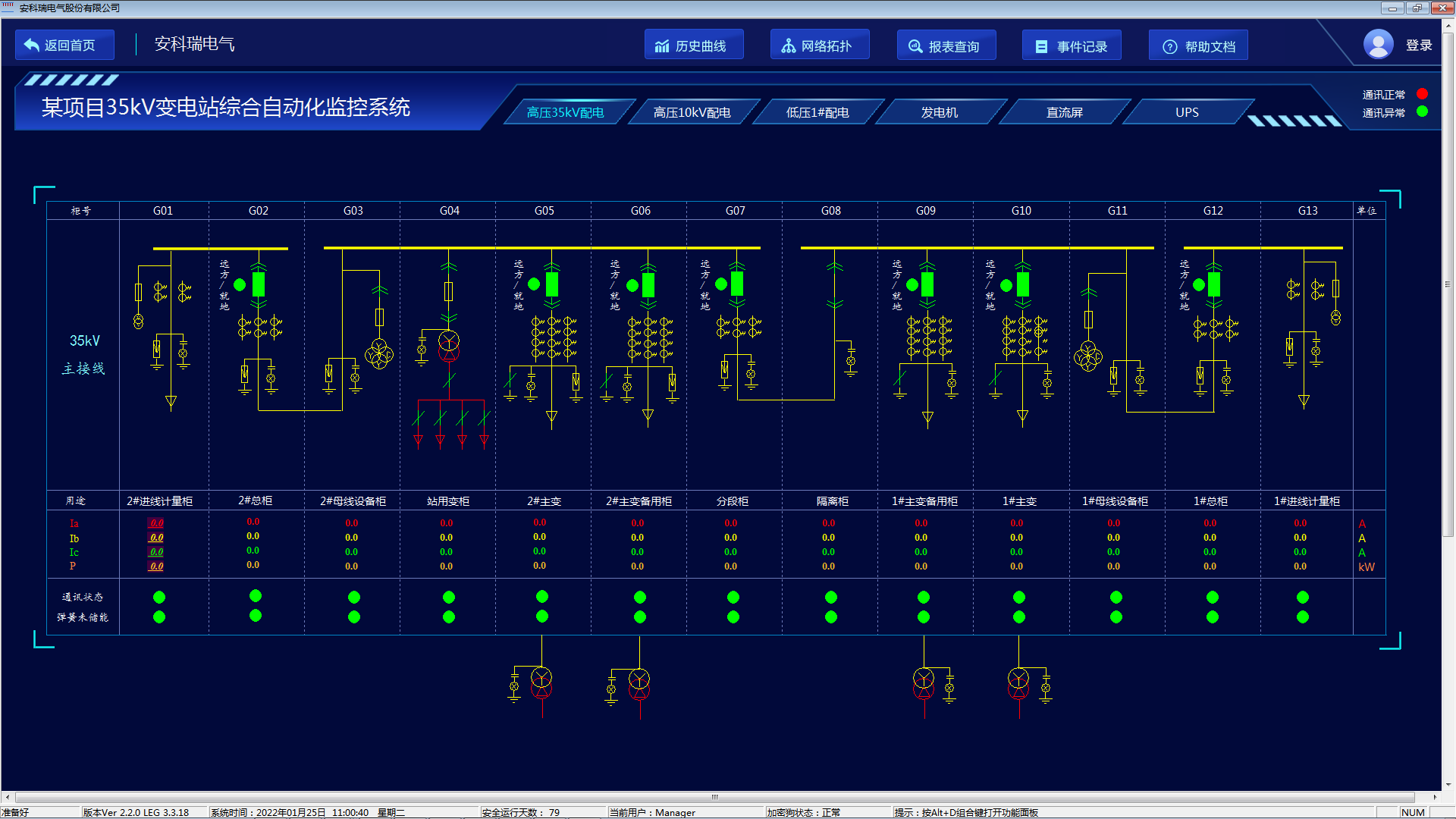
The Acrel-1000 substation comprehensive automation system visually displays the operating status of distribution lines in the form of a distribution primary diagram, monitors real-time electrical parameter information such as voltage, current, power, and power factor of each circuit, dynamically monitors the closing and opening status of circuit breakers, isolating switches, ground knives, and related fault, alarm, and other signals of each distribution circuit.
4.4.2 Alarm Handling
The monitoring system has an accident alarm function. Accident alarm includes circuit breaker tripping and protection device action signals caused by abnormal operation; Pre warning alarms include general equipment displacement, abnormal status information, analog or temperature exceeding limits, etc.
1) Accident alarm. When in the accident state mode, the accident alarm immediately emits an audible alarm (the alarm volume can be adjusted arbitrarily), and the display screen of the operator workstation changes color and flashes to indicate that the device has changed position. At the same time, a pop-up window displays a red alarm text. The alarm is divided into real-time alarm and historical alarm, and the historical alarm text has the function of selecting, querying, and printing.
The accident alarm is manually triggered, and the alarm is confirmed once each time. Once the alarm is confirmed, the sound and flashing will stop.
In the stage of secondary accident alarm occurrence, the next alarm signal is allowed to enter, that is, the secondary alarm does not cover the content of the previous alarm. Alarm processing has the function of defining or exiting on the main computer.
2) For each measurement value (including calculated values), four specified operating limits (physical lower limit, alarm lower limit, alarm upper limit, physical upper limit) are set by the user sequence and defined as pre alarm and accident alarm, respectively.
3) When the switch accident trips or the switch is tripped for the specified number of times, an alarm message will be triggered to prompt the user for maintenance.
4) Alarm method.
The alarm methods have various forms of expression, including pop ups, flashing screens, sound and light alarms, voice, SMS, phone calls, etc., but not limited to the above methods. Users can add or modify alarm information according to their own needs.

4.4.3 Regulation and Control
The operator controls the electrical equipment that needs to be controlled. The monitoring system has operation monitoring function, allowing monitoring personnel to implement monitoring on the operator workstation to avoid misoperation.
The operation control is divided into four levels:
Control, on-site maintenance and control of equipment. Control with priority. When the operator places the remote/local switch of the local equipment in the local position, all other control functions will be locked and only on-site operations will be carried out.
Level control, interval level backup control. The switching between it and the third level control is completed in the interval layer.
Third level control, station control layer control. This level of control is completed on the operator workstation and has the ability to switch between remote/station control layers.
Fourth level control, remote control, priority.
In principle, interval level control and equipment on-site control are used as backup or maintenance operation methods. To prevent misoperation, step-by-step operation is required under any control mode, including selection, returning to school, and execution. Operator and supervisor passwords and line codes should be set at the station level to ensure the safety and correctness of the operation. For any operation method, ensure that the next step is only performed after the previous operation step is completed. Only one control method is allowed at a time.
The equipment included in the control includes: 35kV and below circuit breakers; 35 kV and below isolating switches and grounding switches with live moving mechanisms; Station power 380V circuit breaker; Main transformer tap; Remote reset and remote switching connection piece of relay protection device.
3) Timed control. The operator performs timed control operations on the electrical equipment that needs to be controlled, sets the start and stop times, and completes timed control.
4) Control output of monitoring system. The control output contacts are passive contacts, with a capacity of 110V (220V) and 5A for DC and 220V and 5A for AC.

4.4.4 User Permission Management
The system has set up a user permission management function, which can prevent unauthorized operating systems from defining permission groups for different operation permissions (such as administrators, maintenance personnel, duty personnel groups, etc.), adding usernames and passwords to each permission group, and providing reliable security for system operation, maintenance, and management.

4.5 System Hardware Configuration
| Application scenarios | model | image | protection function | ||
| 35kV Substation Integrated Automation System | Acrel- 1000 |
| Can display the main wiring diagram of the substation, simulate the operation of the distribution network, and achieve unmanned duty mode; Assist operation and maintenance personnel in achieving rapid fault analysis, localization, and troubleshooting based on sequential event records, historical curves, and fault waveforms, in order to minimize power outage time; Real time collection of current, voltage, power, electrical energy, harmonics, voltage fluctuations and other parameters of various circuits and equipment, for energy analysis and energy efficiency management of distribution systems and electrical equipment | ||
| gateway | ANet- 2E8S1 |
| 8-way RS485 serial port, optocoupler isolation, 2-channel Ethernet interface, supports data access of Modbus Rtu, Modbus TCP, DL/T645-1997, DL/T645-2007, CJT188-2004, OPC UA and other protocols, uploads Modbus TCP (master/slave), 104 (master/slave), building energy consumption, SNMP, MQTT and other protocols, supports breakpoint continuation, XML, JSON data transmission, supports standard 8GB SD card (32GB), supports forwarding data to multiple platforms with different protocols; Multiple alarm settings for each device. Input power supply: AC/DC 220V, rail mounted. | ||
| 35kV/10kV/6kV Arc protection | ARB6-A6 |
| Action time: Single criterion for arc light ≤ 3.8ms Dual criteria for arc current ≤ 7.8ms | 0.4kV~35kV: Each section of the busbar is equipped with one main unit. | |
| ARB6-A12 | |||||
| ARB6-A18 | |||||
| ARB6-A24 | |||||
| ARB6-A30 | |||||
| optional | 2. 3-channel Ethernet interface | ||||
| ARB-S0 |
| Passive wide-angle broadband probe (Excluding battery, maintenance free) Comes with built-in filtering function Fully insulated, free of metal components (No electrical safety hazards) Supporting double stranded flame-retardant optical fiber (20 meters) | High voltage cabinet: The busbar room is equipped with one arc light probe, and the handcart room and cable room can each be equipped with one arc light probe as needed. Low voltage cabinet: Install one arc light probe directly facing the main busbar. | ||
| ARB-S1 |
| Passive wide-angle ultraviolet probe (Excluding battery, maintenance free) Comes with built-in filtering function ST standard interface (State Grid Application) Supporting double stranded flame-retardant optical fiber (20 meters) | |||
| 35kV/10kV/6kV Power quality of incoming cabinet online monitoring | APView500 |
| Phase voltage and current+zero sequence voltage and current, voltage and current imbalance, active and reactive power and electrical energy, event alarms and fault recording, harmonics (voltage/current 63rd harmonic, 63rd harmonic between groups, harmonic phase angle, harmonic content, harmonic power, harmonic distortion rate, K factor), fluctuations/flicker, voltage rise, voltage drop, voltage transient, voltage interruption, 1024 point waveform sampling, triggering and timed recording, real-time waveform display and fault waveform viewing, PQDIF format file storage, 32GB memory, 16D0+22D1, communication 2RS485+1RS232+1GPS, 3 Ethernet interfaces (+1 maintenance network interface)+1USB interface supporting USB disk data reading. Supports the 61850 protocol. | ||
| 35kV/100kV/6kV Interval intelligent control Node temperature measurement | ASD500 |
| 5-inch large LCD color screen dynamically displays a simulation diagram and spring energy storage indicator, high-voltage live display and locking, electrical verification, phase verification, 3-channel temperature control and display, remote/local, opening and closing, energy storage knob pre opening and pre closing flashing indicator, opening and closing intact indicator, opening and closing circuit voltage measurement, human body induction, cabinet lighting control, 1-channel Ethernet, 2-channel RS485, 1-channel USB interface, GPS timing, wireless temperature measurement of electrical contacts in the high-voltage cabinet, full electrical parameter temperature measurement, pulse output, 4-20mA output; | ||
| 35kV/10kV/6kV Interval electrical parameter measurement | APM830 |
| Three phase (1, U, kW, kvar, kWh, kvarh, Hz, cos Φ), zero sequence current In, four quadrant electrical energy, real-time and demand, current and voltage imbalance, 66 alarm types and 16 external event (SOE) records each, supporting SD card expansion recording, 2-63rd harmonic, 2D1+2D0, RS485/Modbus, LCD display; | ||
| transformer winding Temperature detection | ARTM-8 |
| 8-way temperature inspection, pre embedded PT100, RS485 interface, 2-channel relay output; | ||
| Transformer joint temperature measurement Low voltage incoming and outgoing cabinet joint temperature measurement | ARTM-Pn-E |
| Wireless temperature measurement collection can be connected to 60 wireless temperature sensors; U. Measurement of all electrical parameters such as I, P, Q, etc; 2-channel alarm output; 1 RS485 communication channel; | ||
| ATE400 |
| Fixed alloy sheet, CT induction power supply, starting current greater than 5A, temperature measurement range -50-125C, measurement accuracy ± 1 ℃; Wireless transmission distance is 150 meters in open space; | |||


| Application scenarios | model | image | protection function | Other functions | |
| 35kV/10kV/ 6kV incoming line | AM6-L |
| Three stage overcurrent protection (with direction and low voltage lockout), overload protection, PT disconnection alarm, reverse power protection, three-phase primary reclosing, low-frequency load shedding, synchronous detection, loop closure protection, and circuit breaker failure protection; | Operating circuit Dual Ethernet ports Dual 485 ports 2-channel 4-20mA transformer Send output Fault recording GPS timing Full power measurement DC measurement
| |
| 35kV/10kV/ 6kV feeder line | AM6-L | Three stage overcurrent protection (with direction and low voltage lockout), overload protection, PT disconnection alarm, reverse power protection, three-phase primary reclosing, low-frequency load shedding, synchronous detection, loop closure protection, and circuit breaker failure protection; | |||
| 35kV main transformer (Above 2000kVA) | AM6-D2/ AM-3 | Two turn/three turn differential quick break protection, proportional braking differential protection; | |||
| AM6-TB | Transformer backup protection measurement and control, three-stage overcurrent protection (with direction and composite voltage locking), non electric quantity protection, starting ventilation protection, PT disconnection alarm, remote adjustment upshift, remote adjustment downshift, remote adjustment emergency stop; | ||||
| 35kV/10kV/ 6kV plant transformer | AM6-S | Three stage overcurrent protection (with directional and composite voltage locking), zero sequence overcurrent, overload protection (alarm/trip), control fault alarm, PT disconnection alarm, non electricity protection; | |||
| 35kV motor (Above 2000kW) | AM6-MD | Comprehensive motor protection including differential quick break protection, proportional differential protection, overcurrent, overload, and locked rotor protection; | |||
| 10kV/6kV asynchronous motor | AM6-M | Two stage overcurrent/zero sequence overcurrent/negative sequence overcurrent protection, overload protection (alarm/trip), low voltage protection, PT disconnection alarm, locked rotor protection, startup timeout, thermal overload protection, voltage imbalance; | |||
| 35kV/10kV/6kV PT monitoring | AM6-UB | PT parallel/disconnection, PT monitoring; | |||
| 10kV/6kV capacitor | AM6-C | Two stage overcurrent/zero sequence overcurrent protection, overload protection (alarm/trip), PT disconnection alarm, overvoltage/undervoltage trip, unbalanced voltage/current protection; | |||
| 35kV/10kV/ 6kV bus tie | AM6-B | Two line backup/bus coupling backup/adaptive backup, coupling switch backup, three-stage overcurrent protection (with direction and composite voltage lockout), PT disconnection alarm, overload coupling switch/alarm, synchronous detection, and loop closing protection; | |||


5 Summary
Scientific and rational substation design is the foundation for ensuring its safe and reliable operation, and attention should be paid to site selection, equipment selection, and automation system design; Operational management strategies and energy efficiency optimization measures can significantly improve the operational efficiency and economic benefits of substations; In the future, with the development of smart grid technology, large industrial enterprise substations will move towards a more intelligent and automated direction, providing more reliable power supply for enterprises.