-
E-mail
2802943235@qq.com
-
Phone
18702111683
-
Address
No. 253 Yulu Road, Jiading District, Shanghai
Ankerui Electric Co., Ltd
The new green electricity policy will be implemented in 2025! How can smart park microgrids "save electricity costs and earn carbon money"?
Date: 2025-11-11Read: 27
Introduction: The Era Opportunity of Connecting Smart Parks and Green Electricity Directly to Microgrids (2025 Policy Empowerment Edition)
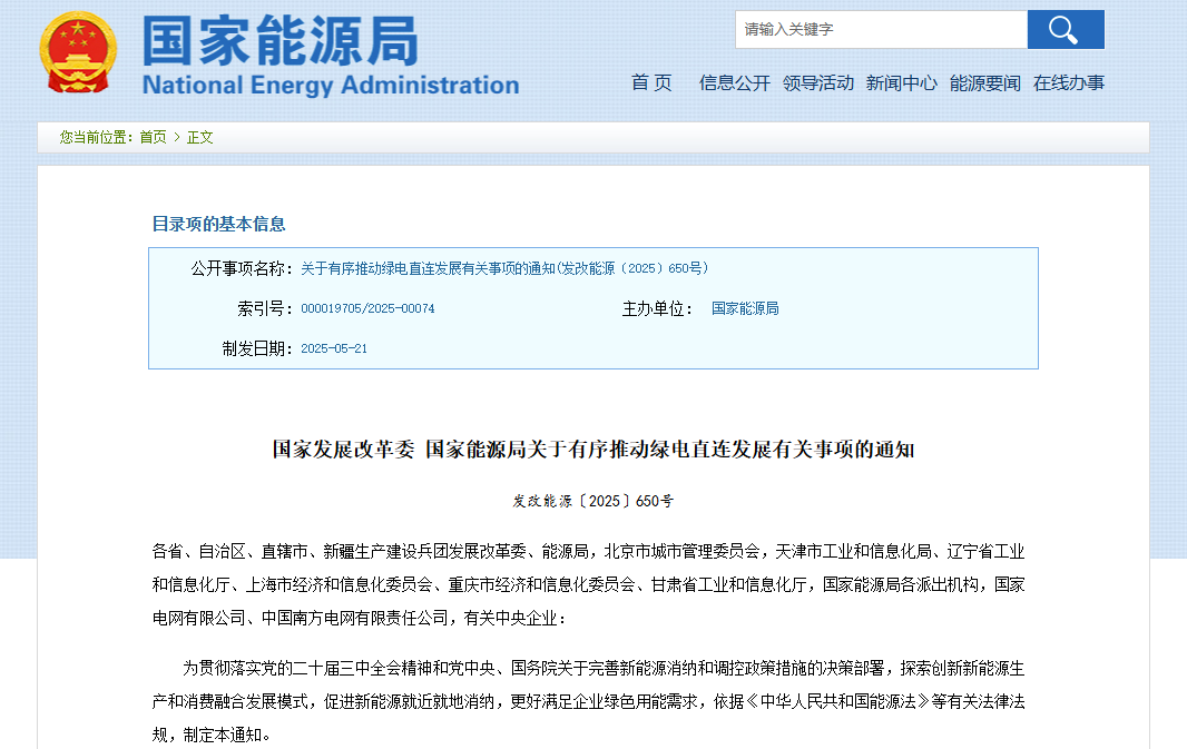
Driven by the global energy transition and the "dual carbon" goals, the traditional energy system is accelerating its transformation towards cleanliness and intelligence. Industrial parks are centers of energy consumption and carbon emissions, and innovative energy management models are key to achieving low-carbon development. In 2025, China's smart microgrid policy will make significant breakthroughs, and the National Development and Reform Commission and the National Energy Administration will jointly issue a notice on promoting the orderly development of green power direct connectionClarify the definition, construction requirements, and market position of the green power direct connection mode, and provide top-level design for the green power direct connection microgrid system in smart parks. This policy is in line with the expansion of the global microgrid market, and China is using policy guidance and technological breakthroughs to accelerate the implementation of smart microgrids in multiple scenarios. From 2024 to the first quarter of 2025, 210 domestic microgrid projects will be connected to the grid, with a total investment of over 2.7 billion yuan. It is expected that by 2030, over 50% of industrial parks will achieve full coverage of microgrids. In this context, the direct connection of green electricity to microgrids in smart parks is not only a technological innovation, but also a product of energy revolution and industrial upgrading“inevitably”choice.
1、 System Definition and Core Values
The smart park green power direct connected microgrid system is a regional energy network that integrates renewable energy generation (such as photovoltaic and wind power), energy storage devices (such as lithium batteries and supercapacitors), intelligent load management (such as air conditioning and charging stations), and digital control technology. Its core goal is to directly supply green electricity to end users in the park through "physical direct connection" or "virtual direct connection", achieving precise matching of electricity supply and demand, optimization of energy costs, and reduction of carbon emissions.
Core value of the solution:
①Energy Security and Independence
Reduce dependence on traditional power grids: By coordinating distributed power sources and energy storage systems, the reliability of power supply in the park can be improved, and the risk of shutdown caused by power grid failures can be reduced.
Dealing with bad weather: In the disaster scenarios such as typhoon and rainstorm, the micro grid can be switched to off grid mode to ensure the continuous power supply of key loads (such as hospitals and data centers).
②Economy and Cost Optimization
Peak valley electricity price arbitrage: Energy storage systems charge during low valley periods and discharge during peak periods, reducing the maximum demand and basic electricity costs of the park (such as a copper project in Ningbo that saves over 3 million yuan in electricity costs annually).
Green electricity trading value-added: By participating in electricity market transactions or purchasing green electricity certificates, enterprises can obtain green electricity premiums and enhance product environmental competitiveness.
③Environmental benefits and carbon reduction
Renewable energy consumption: directly using clean electricity such as photovoltaics and wind power to reduce fossil energy consumption (such as a company's microgrid reducing carbon dioxide emissions by 2000 tons per year).
Carbon asset development: The system has a built-in carbon management module that calculates carbon emissions in real-time, supports enterprises to participate in the carbon trading market, and realizes the realization of carbon assets.
④Intelligent management and operational efficiency
Real time monitoring and prediction: relying on big data and AI algorithms, achieve energy equipment status monitoring, load forecasting, and optimized scheduling (such as the ultra short term load forecasting function of the AcrelEMS system of Ankerui).
Automated control: By using intelligent networked devices such as air conditioning controllers and smart meters, manual intervention is reduced and maintenance costs are lowered.
⑤Policy Compliance and Market Competitiveness
Meet the "dual carbon" goal: help park enterprises achieve policy requirements such as reducing carbon emission intensity and increasing the proportion of renewable energy.
Enhancing brand image: Green energy supply can enhance corporate ESG (environmental, social, governance) performance, attract investment and partners.

II Solution Networking Architecture
The networking architecture of Ankerui EMS3.0 system solution mainly coversparkThe various links of "source grid load storage charging" in microgrids,Realized integrated flexible control of source network load storage and charging, as well as interconnection, intercommunication, and interaction. It can monitor, intelligently predict, dynamically allocate, optimize strategies, diagnose and alert the operating status of distributed power sources, municipal power sources, energy storage systems, charging facilities, and various AC/DC loads in enterprise microgrids in real time, achieving orderly interaction between dispatchable sources and loads and comprehensive energy analysis, meeting the needs of digital energy efficiency management, intelligent safety analysis, dynamic adjustment and control, and visualized panoramic analysis of enterprise microgrids.
Equipment layer:Integrate multifunctional instruments, protective devices, energy storage and new energy equipment (such as photovoltaic and wind power generation), charging piles, etc., and achieve real-time collection and transmission of equipment data through diversified communication interfaces and protocols.
Transport layer:Adopting a data fusion terminal that supports multi protocol conversion and data encryption, ensuring stable and secure transmission of data to the cloud platform.
Cloud platform layer:Centralized storage, processing, and display of data, providing functions such as energy monitoring, historical data analysis, and alarm notifications. At the same time, open API interfaces to facilitate third-party system integration.
Application layer:Based on cloud platform data, applications such as energy planning, energy storage optimization, and orderly charging are implemented, supporting users to access and enjoy convenient energy management services through multiple terminals.

III System feature interface display
3.1 Real time monitoring
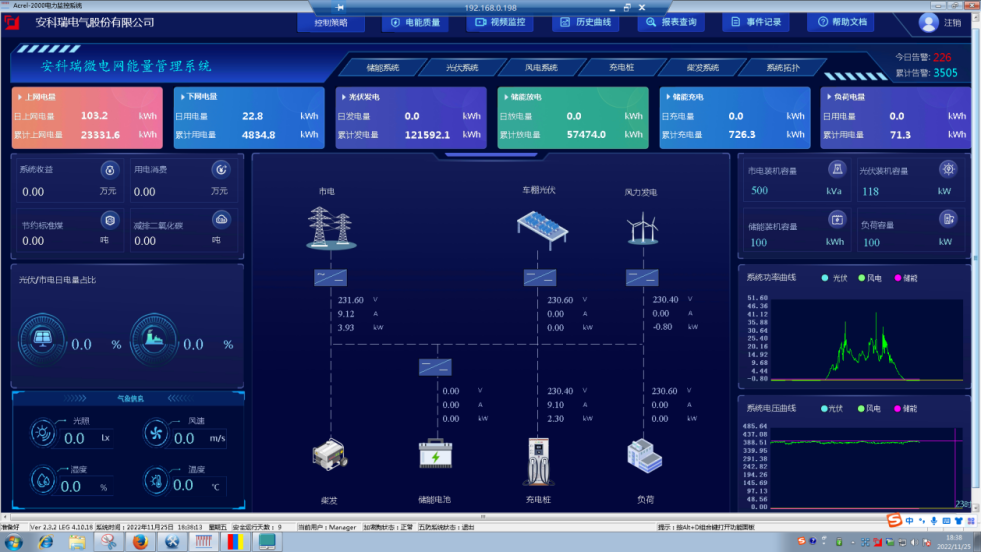
The monitoring system interface of the microgrid energy management system includes the system main interface, which includes the microgrid photovoltaic, wind power, energy storage, charging piles, and overall load composition, including revenue information, weather information, energy conservation and emission reduction information, power information, electricity quantity information, voltage and current situation, etc. According to different needs, charging, energy storage, and photovoltaic system information can also be displayed.
3.2 Photovoltaic Interface
Display information on photovoltaic systems, mainly including monitoring and alarm of the operating status of inverters on the DC and AC sides, statistics and analysis of inverter and power station power generation, monitoring and analysis of grid connected cabinet power generation, statistics of annual effective utilization hours of power station power generation, statistics of power generation revenue, carbon emission reduction statistics, monitoring of irradiance/wind power/environmental temperature and humidity, simulation and efficiency analysis of power generation; Simultaneously display the total power, voltage and current of the system, as well as the operational data of each inverter.
3.3 Energy storage interface
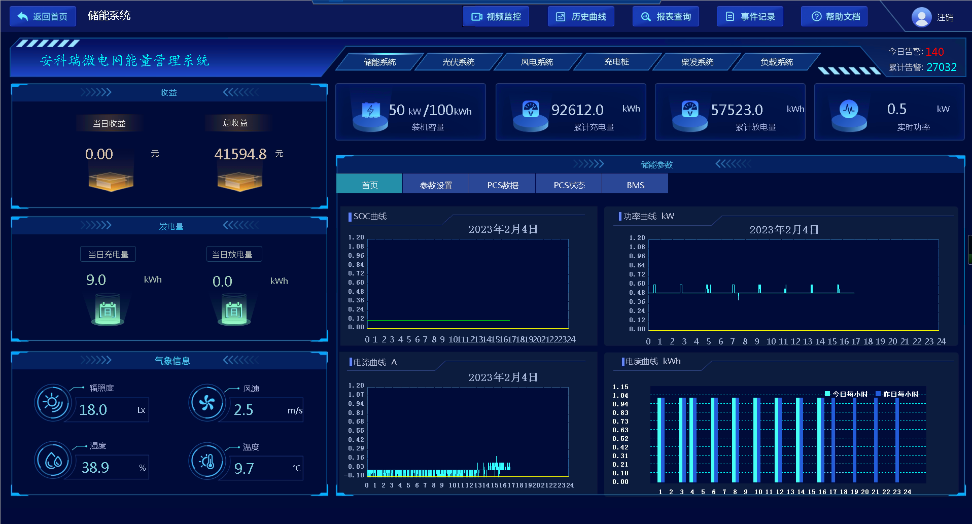
Display the energy storage installed capacity, current charging and discharging capacity, revenue, SOC change curve, and electricity change curve of this system. Data display and control of PCS and BMS.
3.4 Wind Power Interface
Display information on wind power systems, mainly including monitoring and alarm of the operation status of the DC and AC sides of the inverter control integrated machine, statistics and analysis of the power generation of the inverter and the power station, statistics of the annual effective utilization hours of the power station's power generation, statistics of power generation income, carbon reduction statistics, monitoring of wind speed/wind speed/environmental temperature and humidity, simulation of power generation and efficiency analysis; Simultaneously display the total power, voltage and current of the system, as well as the operational data of each inverter.

3.5 Charging Station Interface
Display information about the charging station system, mainly including the total power consumption of charging stations, the power and electricity consumption of AC and DC charging stations, electricity costs, change curves, and operational data of each charging station.

3.6 Power generation forecast
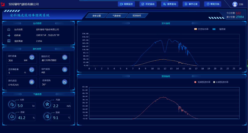
Based on historical power generation data, measured data, and future weather forecast data, predict the short-term and ultra short term power generation of distributed power generation, and display the qualification rate and error analysis. According to power prediction, manual input or automatic generation of power generation plans can be carried out, which facilitates users to centrally control the new energy generation of the system.
3.7 Strategy Configuration
The system should be able to set the system operation mode and configure different control strategies based on power generation data, energy storage system capacity, load demand, and time of use electricity price information. Such as peak shaving and valley filling, cycle planning, demand control, anti backflow, orderly charging, dynamic expansion, etc.

3.8 Real-time alarm
Equipped with real-time alarm function, the system should be able to remotely signal the starting and closing of inverters and bidirectional converters in each subsystem, as well as issue alarms when internal protection actions or accident trips occur. It should be able to display alarm events or trip events in real time, including the name of the protection event and the time of the protection action; And it should be able to notify relevant personnel in the form of pop ups, sounds, text messages, and phone calls.

3.9 Power Quality Monitoring
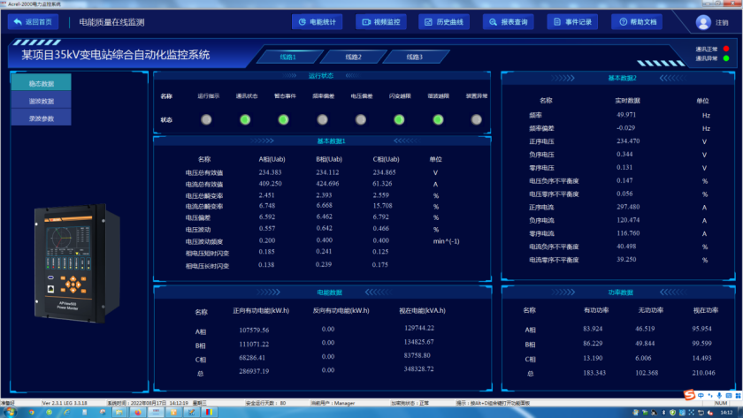
Continuous monitoring of the power quality of the entire microgrid system, including steady-state and transient states, enables management personnel to grasp the power quality situation of the power supply system in real time, in order to timely detect and eliminate unstable power supply factors.
3.10 Network Topology Diagram
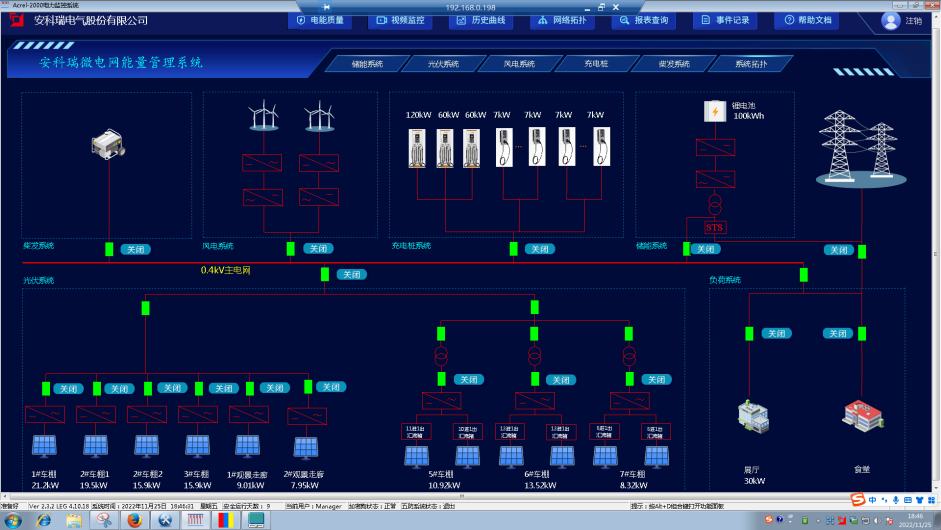
The system supports real-time monitoring of the communication status of various devices connected to the system, and can fully display the entire system network structure; It can diagnose the communication status of equipment online, and automatically display the faulty equipment or component and its faulty location on the interface when network abnormalities occur.
3.11 Fault recording
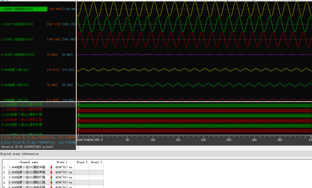
When the system malfunctions, it automatically and accurately records the changes in various related electrical quantities before and after the fault. By analyzing and comparing these electrical quantities, it plays an important role in analyzing and handling accidents, determining whether the protection is operating correctly, and improving the safe operation level of the power system. Among them, a total of 16 fault waveforms can be recorded, and each waveform can trigger 6 segments of waveform recording. Each waveform recording can record 8 cycles before the fault and 4 cycles after the fault, with a total recording time of 46 seconds. Each sampling point recording should include at least 12 analog waveforms and 10 switch waveforms.
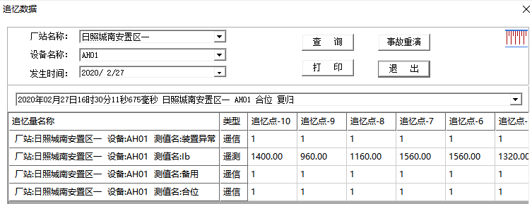
3.12 Accident Remembrance
It can automatically record all real-time scanning data before and after the accident, including switch position, protection action status, remote measurement, etc., forming the data basis for accident analysis;
Users can customize the start event for accident recall, and when each event occurs, store relevant point data for the first few scan cycles before the accident and 10 scan cycles after the accident. The data points for initiating events and monitoring can be specified and modified by users at will.
4 Typical product recommendations
| serial number | name | picture | model | Functional Description | Usage scenarios |
| 1 | Microcomputer protection device |
| AM6、AM5SE | Protection and measurement devices for circuits such as 110kV and below voltage levels, main transformers, motors, capacitors, busbars, etc | 110kV、35kV、10kV |
| 2 | Online monitoring device for power quality |
| APView500 | Integrating harmonic analysis/waveform sampling/voltage flicker monitoring/voltage imbalance monitoring, transient monitoring such as voltage sag/rise/short interruption, event recording, measurement control and other functions, it meets the * * power quality assessment standards and can meet the requirements of power quality monitoring for 110kV and below power supply systems | 110kV、35kV、10kV、0.4kV |
| 3 | Anti islanding protection device |
| AM5SE-IS | Relay protection measures to prevent unplanned continuous islanding operation of distributed power generation systems connected to the grid, and to prevent islanding effects in the power grid. The device has protection functions such as low voltage protection, overvoltage protection, high frequency protection, low frequency protection, reverse power protection, synchronous detection, and voltage closing | 110kV、35kV、10kV、0.4kV |
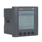
| 4 | multi-function meter |
| APM520 | Full power parameter measurement, multi rate energy metering, four quadrant energy metering, harmonic analysis, and energy monitoring and assessment management. Interface function: equipped with RS485/MODBUS protocol | Grid connected cabinets, incoming cabinets, bus tie cabinets, and important circuits |
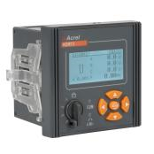
| 5 | multi-function meter |
| AEM96 | It has full power measurement, harmonic distortion rate, time-sharing energy statistics, switch input and output, and analog input and output. | Mainly used for energy metering and monitoring |
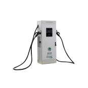
| 6 | Electric vehicle charging station |
| AEV200-DC60S AEV200-DC80D AEV200-DC120S AEV200-DC160S | Output power of 160/120/80/60kW DC charging station, meeting the needs of fast charging. | Charging station operation and charging control |
| 7 | Input/output module |
| ARTU100-KJ8 | Can collect 8 switch signals and provide 8 relay outputs | Signal acquisition and control output |
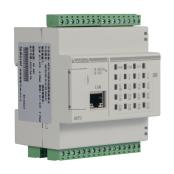
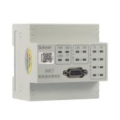
| 8 | Smart Gateway |
| ANet-2E4SM | Edge computing gateway, embedded linux system, network communication mode with Socket mode, support XML format compression upload, provide security requirements such as AES encryption and MD5 identity authentication, support breakpoint continuous transmission, support Modbus, Modbus TCP, DL/T645-1997, DL/T645-2007, 101, 103, 104 protocols | Data collection, conversion, and logical judgment of electricity, environment, and other data |
| 9 | Energy management of energy storage cabinet |
| Acrel-2000ES | The energy storage management system has comprehensive energy storage monitoring and management functions, covering detailed information of energy storage system equipment (PCS, BMS, electricity meters, fire protection, air conditioning, etc.), realizing functions such as data collection, data processing, data storage, data query and analysis, visual monitoring, alarm management, statistical reporting, etc. Supports energy scheduling in advanced applications, with control functions such as planning curves, peak shaving and valley filling, demand control, and backflow prevention. | Specially designed for industrial and commercial energy storage cabinets and containers |
| 10 | Microgrid Strategy Coordination Controller |
| ACCU-100 | The microgrid coordination controller can be connected to devices such as photovoltaic, wind power, energy storage, and charging piles, collect and analyze data 24/7, monitor operation and health status, and obtain the most effective strategy with the goal of safe and economic operation. It implements regulation and control, realizes real-time dynamic adjustment of distributed energy, energy storage, and load, promotes on-site consumption of new energy, improves grid stability, compensates for load fluctuations, effectively manages demand, improves operational efficiency, reduces costs, and ensures safe, reliable, and economic operation of microgrids. | Applied in microgrids, distributed generation, energy storage and other fields |
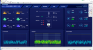
| 11 | Microgrid Smart Energy Platform |
| Acrel-EMS3.0 | The platform provides real-time monitoring of the operating status of distributed power sources, municipal power sources, energy storage systems, charging facilities, and various loads in enterprise microgrids, as well as energy analysis, intelligent prediction, dynamic allocation, optimization strategies, diagnostic alarms, orderly interaction between dispatchable sources and loads, and energy panoramic analysis. It meets the needs of digital energy efficiency management, intelligent safety analysis, dynamic adjustment and control, and visualized panoramic analysis in enterprise microgrids, achieving flexible interaction and economic operation between photovoltaic storage and charging resources under different strategies, reducing user energy costs, and improving the operational efficiency of enterprise microgrids. | Operation of distributed power sources, municipal power sources, energy storage systems, charging facilities, and various loads in enterprise microgrids |




Conclusion:
The vigorous rise of green power direct connected microgrid systems in smart parks symbolizes a profound transformation of energy management from "passive response to supply" to "active intelligent optimization". It not only customizes cost-effective, green and environmentally friendly energy solutions for the park, but also redefines the interactive relationship between energy production and consumption through the deep integration of digitization and intelligence. With the continuous innovation and breakthroughs in technology and the continuous improvement and optimization of policy systems, microgrids are gradually becoming a key support for building a new type of power system and helping to achieve the "dual carbon" goals.
Looking ahead to the future, with the increasing maturity of the green power trading market, the widespread adoption of virtual power plant technology, and the user side energy management moving towards refinement and intelligence, the green power direct connected microgrid system in smart parks will further explore and unleash its enormous potential, and the energy revolution will move towards a deeper and more comprehensive new stage. In this historic process, parks, enterprises, and governments need to work together to explore and practice sustainable energy development paths, contributing distinctive Chinese wisdom and practical Chinese solutions to the global green transformation.