-
E-mail
chenghaixia@email.acrel.cn
-
Phone
18217358524
-
Address
No. 253 Yulu Road, Jiading District, Shanghai
Ankerui Electric Co., Ltd
Distributed photovoltaic anti backflow: from technology to implementation, ensuring that every kilowatt hour of electricity does not flow backwards
Date: 2025-11-07Read: 18
1. Solution Description
With the increasing installation of distributed photovoltaics, red zones have emerged in some areas. Local power companies require the construction of new distributed photovoltaics for self use and the implementation of anti backflow measures to meet the regulations and requirements of local power companies.
lPolicy promotion
According to the "Management Measures for the Development and Construction of Distributed Photovoltaic Power Generation" issued by the National Energy Administration,6MWDistributed photovoltaics above and above require all to be self generated and used6MWThe following distributed photovoltaics require a mode of self use and surplus electricity grid connection. For some areas where there are restrictions on the installation of distributed photovoltaics, some are less than6MWDistributed photovoltaics also require spontaneous self use and anti backflow control requirements.
In order to achieve the above goals, a scheme for preventing backflow, namely a coordinated controller, is proposedACCU-100Combined with anti backflow protection deviceAM5SE-ISThe plan is to monitor the backflow situation at the public connection point. Once backflow is detected or is about to occur, a signal will be sent to the coordination controller through the communication interface. The coordination controller monitors the power at the main incoming line of the mains and real-time power generation, and generates corresponding inverter adjustment instructions through system calculation to achieve flexible regulation of photovoltaic backflow prevention. At the same time, reverse power or low power protection functions are installed in the anti backflow protection device as a flexible control for backflow protection in case of loss of control. This method can ensure that the power system operates according to design, protect the safety and stability of the power grid, and maximize the utilization of photovoltaic power generation.
lPhotovoltaic anti backflow position
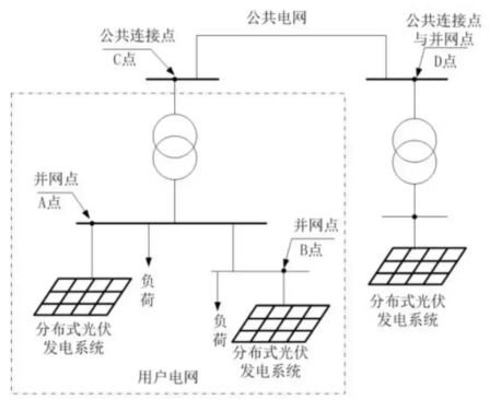
As shown in the figure1As shown, the dashed box represents the user's power grid, which is connected through a common connection pointCConnected to the power grid. Within the user's power grid, there are two distributed photovoltaic power generation systems, each of which utilizesAPoint andBThe point is connected to the user's power grid,APoint andBAll points are connection points, but not public connection points. inDDistributed photovoltaic power generation systems are directly connected to the public power grid,DA point is a branch point and also a public connection point. Therefore, the anti backflow of distributed photovoltaics should be monitored at the common connection point(CorDThe internet power at the point.
lNational standard requirements
According to《GB/T 50865-2013Design Specification for Photovoltaic Power Generation Connected to Distribution Network《GB/T 29319-2012The national standards such as the Technical Regulations for the Connection of Photovoltaic Power Generation Systems to Distribution Networks clearly state the requirement for anti backflow: when the photovoltaic power generation system is designed for irreversible grid connection, reverse power protection equipment should be configured. When the reverse current is detected to exceed the rated output5%At that time, the photovoltaic power generation system should2sAutomatically reduce output or stop supplying power to the grid lines.
1. Scheme composition
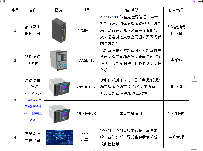
The main product list is as follows:
(1)ACCU-100Microgrid Coordination Controller
By monitoring the anti backflow signal at the main incoming line of the municipal power supply, upload the electrical signal of the municipal power supply toACCU-100Microgrid Coordination Controller. The controller will perform precise logical calculations on the reverse flow data, and adjust the output power of the inverter accordingly, ultimately achieving no reverse flow operation.
ACCU-100Closely cooperate with the smart energy management cloud platform to build an efficient system architecture. The controller precisely regulates distributed energy and interacts in real-time with cloud platforms, responding to cloud strategy configuration, achieving cross site and cross regional massive data access and analysis, providing precise control and optimal control solutions for each site, and further improving management efficiency through remote monitoring and operation functions.
(2)Anti backflow protection device
To ensure the reliability of the system, the anti backflow protection device is configured to quickly cut off or rotate the grid connected cabinet circuit breaker in case of abnormal situations such as controller failure or communication interruption, ensuring the safety of the power grid. There are currently anti backflow protection devices available2The selection can be based on the application scenario.
1)The distance between the grid connection point and the backflow detection point is relatively close(suggestion200mWithin)
OptionalAM5SE-ISAnti backflow protection device, equipped with reverse power tripping and reverse power recovery closing; Low power tripping, low power recovery closing.
2)The distance between the grid connection point and the backflow detection point is relatively far (exceeding200m)
OptionalAM5SE-PVSeries master-slave anti backflow protection device. Having: master-slave scheme with four stages of low power/Low power restoration closing; Reverse power of master-slave scheme/Reverse power restoration closing; Host anti islanding protection and slave anti islanding protection.
3)Smart Energy Management Platform
with the help of AcrelEMS 3.0The smart energy management platform can conduct real-time monitoring of the photovoltaic power generation system and electricity load of the user's microgrid. Combined with advanced photovoltaic prediction technology, this platform can optimize operational strategies and achieve orderly interaction between sources and loads. Not only can it flexibly adjust the output of the inverter, effectively avoiding backflow, but it can also fully meet the needs of enterprise microgrids in energy efficiency management digitization, safety analysis intelligence, and significantly improve the operational efficiency and energy utilization of microgrids.
1. Scheme wiring
(1)The wiring diagram of the anti backflow protection device for single incoming and single parallel points is shown in the figure2As shown.
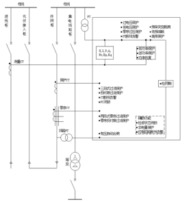
Picture2 Wiring diagram of AM5SE-IS anti backflow protection device
(2)Multiple connection points for a single incoming line, and the distance between the anti backflow point and the connection point exceeds200The wiring diagram of the anti backflow protection device of Mi is shown in the figure3As shown.
If there are multiple grid connection points for the incoming power line, the host should be selectedAM5SE-PVMSelection of slave machinesAM5SE-PVS(*maximum support1main5From), as shown in the figure3As shown.
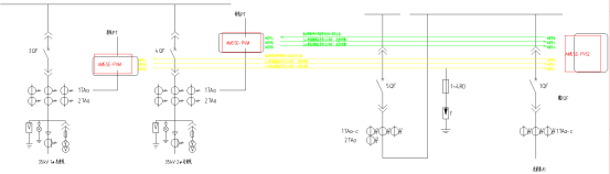
Picture3 AM5SE-PV master-slave scheme anti backflow protection device wiring diagram (1)
(3)Multi entry single line/Multiple grid connection points, and the distance between the anti backflow point and the grid connection point exceeds200The wiring diagram of the anti backflow protection device of Mi is shown in the figure4As shown.
When the mains power input is a multi-channel power input strip1Or multiple grid connection points, host selectionAM5SE-PVMSelection of slave machinesAM5SE-PVS2(1A host*More support5A slave machine1A slave machine*Accept more4A host, as shown in the figure4As shown.
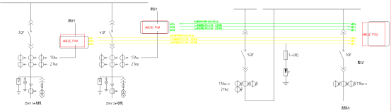
Picture4 AM5SE-PV master-slave scheme anti backflow protection device wiring diagram (2)
1. Scheme networking
By installing anti backflow devices at the mains power inlet (for multi inlet and multi grid connection points, master-slave anti backflow devices can be used), real-time monitoring of the photovoltaic grid connection situation can be carried out, and the monitoring signals can be uploaded to the coordination controller. By logically calculating the reverse flow data, the output power of the inverter is adjusted to achieve no reverse flow situation.
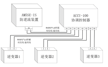
Picture5 Coordination Controller and Protection Device Networking Wiring Diagram
2. data collection
According to the on-site environment, collect data from the equipment required for photovoltaic backflow prevention.
1)City power connection point
Main function: Monitor real-time interactive power of the municipal power supply.
Related equipment: gateway meter or anti backflow protection device.
2)Photovoltaic grid connected cabinet
Main function: Monitor the real-time power, communication status, and operation status of photovoltaic equipment.
Related equipment: photovoltaic grid connected electricity meter, circuit breaker status.
Equipment relationship: There may be multiple photovoltaic units under the photovoltaic node.
3)Photovoltaic unit
Main function: Execute photovoltaic power regulation commands.
Related equipment: photovoltaic inverterSmartLogger(Huawei data collector, capable of batch control of photovoltaic inverters).
3. Control instructions
(1)Anti backflow protection device protection part
According to the actual situation on site, the parameters of the anti backflow protection device are adjusted in a segmented manner. When the flexible adjustment fails or the response is not timely, the anti backflow protection device will trip to avoid assessment and fines. After monitoring the disappearance of backflow, it will be re closed.
The reference for setting the protective device is as follows:
1)Design Specification for Photovoltaic Power Generation Connected to Distribution NetworkGB/T 50865-2013,6.3.2When the photovoltaic power generation system is designed for irreversible grid connection mode,Reverse power protection equipment should be configured. When the reverse current is detected to exceed the rated output5%At that time, the photovoltaic power generation system should2sAutomatically reduce output or stop supplying power to the grid lines.
2)Technical Standards for Application of Building Photovoltaic Systems[Supplementary Article Explanation]How to translateGB/T 51368-2019 8.9.3The grid connected automation system for building photovoltaic systems should comply with the following regulations: When the building photovoltaic system is designed for irreversible grid connection, reverse power protection equipment should be configured. Reverse power protection should have the ability to detect reverse current exceeding the rated output5%At that time, building photovoltaic systems should be
2s
1Automatically reduce output or stop supplying power to the grid lines.2.5The project considers the time difference and appropriate margin for feedback regulation, and the parameters of the anti backflow protection device are set as follows:)Allow partial reverse flow: Reverse power protection is based on the detection of reverse current exceeding the rated output%When, the building photovoltaic system follows the
22sAutomatic reduction of output or cessation of power transmission to the power grid line for internal adjustment.)No backflow allowed: The reverse power protection is set to low power according to the difference in load fluctuations, and the time is based on the collection time
+2Set the sum of the operation time of the inverter equipment.
(
| )Flexible adjustment part | The parameter definitions are as follows: | name |
| description | ||
| equipment | real-time value | p_cc |
| Power of mains connection point | Gateway meter or anti backflow device | p_pv |
| Actual total photovoltaic power generation | grid-connected cabinet | p_pv_rp |
| Effective total rated power of photovoltaic system | Photovoltaic unit | pv_state_1 |
| Communication status of photovoltaic unit | Photovoltaic unit | pv_state_2 |
| Normal grid connection status of photovoltaic units (corresponding to limited grid connection) | Photovoltaic unit | DL_state_1 |
| Grid connected cabinet circuit breaker (multiple similar types) | grid-connected cabinet | pv_mode |
| Photovoltaic unit operation mode | ||
| Photovoltaic unit | Setpoint | |
| p_cc_set_min | Reduce the photovoltaic power threshold (this value needs to be higher than the setting value of the anti backflow protection device) | |
| p_cc_set_max | Power recovery threshold | |
| p_coef | power coefficient | |
| p_dead_line | Photovoltaic power dead zone prevents frequent triggering of photovoltaic power reduction | |
p_pv_rate_maxUpper limit of photovoltaic power regulation ratio
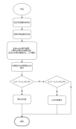
1. lDetailed process for reducing photovoltaic power:Calculate photovoltaicseffectiveTotal rated power,
2. Communication status is normal and operating mode
3. Normal is effective;Verify the effectiveness of rated power (greater than zero);
Calculate the issued power p_rate
4. p_rate = (p_pv - (p_cc_set_min - p_cc) - p_dead_line) / p_pv_rp;Verify the issued power
5. p_rate
6. Validity (greater than or equal to zero);
7. Issuing power coefficient processing;
Allow power verification to be issued (must be different from the last issued power);Distribute power and perform batch remote setting.
1. l
2. Detailed process of photovoltaic power restoration:Verify whether the photovoltaic unit can increase power (whether it has been connected to the grid normally)Calculate photovoltaicseffectiveTotal rated power,Normal communication and operating modeNormal and
3. Not in normal grid connection state
4. To be effective;Verify the effectiveness of rated power (greater than zero);Reasonability judgment of return step size
,*Prevent excessive adjustment range from causing backflow p_pv_rp
5. p_pv_step< p_cc_set_max - p_cc_set_min
Calculate the issued power p_rate p_rate = (p_pv / p_pv_rp) +
6. p_pv_step;Verify the issued power
7. p_rateEffectiveness (greater than or equal to zero and less than the upper limit of photovoltaic power regulation ratio);
8. Issuing power coefficient processing;Allow power verification to be issued(need
9. Different from the last power issue)
;