-
E-mail
312534289@qq.com 467090947@qq.com
-
Phone
18761882890/13814089468
-
Address
15-20 Xingda Road, Nanjing Yangtze River Industrial Development Zone
Product Categories
- Ultrasonic water meter
- parshall flume
- Residual chlorine analyzer
- COD
- Electromagnetic Flowmeter
- CONDUCTIVITY METER
- Ultrasonic Heat meter
- Sludge concentration meter
- Ultrasonic Open Channel Flowmeter
- Ultrasonic level gauge
- PH meter
- ultrasonic flowmeter
- Dissolved oxygen analyzer
- doppler flow meter
- current meter
- Ultrasonic depth sounder
Nanjing Zhuoma Electromechanical Co., Ltd

TDS-100P portable ultrasonic flowmeter with printing
NegotiableUpdate on 06/02
- Model
- Nature of the Manufacturer
- Producers
- Product Category
- Place of Origin
Overview
Left side view of the outline drawing: Section 1.4 Working principle TDS-100P portable ultrasonic flowmeter is used to measure liquid flow in closed pipelines. Its sensor is non-contact and attached, making installation simple and easy to operate. The two sensors of the TDS-100P portable ultrasonic flowmeter have the characteristics of both receiving and transmitting. Users can attach two sensors to the outside of the pipeline at a certain distance, using the V-method with two sound paths, the W-method with four sound paths, or the Z-method with relative installation where sound waves directly pass through the tested pipeline. Traffic
Product Details
>
Outline drawing

Left side view:

The TDS-100P portable ultrasonic flowmeter is used to measure liquid flow in closed pipelines. Its sensor is non-contact and attached, making installation simple and easy to operate.
The two sensors of the TDS-100P portable ultrasonic flowmeter have the characteristics of both receiving and transmitting. Users can attach two sensors to the outside of the pipeline at a certain distance, using the V-method with two sound paths and the W-method with four sound paths,
Alternatively, the Z-method of relative installation can be used by directly passing sound waves through the tested pipeline.
The flow meter controls two sensors to alternately receive and emit ultrasonic waves and measure the propagation time between them. The time difference is calculated, and the obtained time difference is proportional to the flow velocity of the fluid, which follows the following expression:

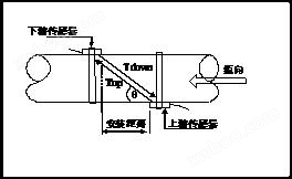 θ is the angle between the sound beam and the direction of liquid flow
M is the number of straight line propagation times of the sound beam in the liquid
D is the inner diameter of the pipeline
Tup is the propagation time of the sound beam in the positive direction
Tdown is the propagation time of the sound beam in the opposite direction
ΔT=Tup –Tdown
§ 1.5 Typical Applications|
1. |
Water, industrial wastewater, seawater |
10. |
Ship operation and maintenance |
|
2. |
Acid-base solution |
11. |
Energy saving monitoring and water-saving management |
|
3. |
Various oils |
12. |
Paper and pulp making |
|
4. |
Water supply and drainage |
13. |
Leak detection |
|
5. |
Water resource detection |
14. |
Heating, Heating, Heating |
|
6. |
Petroleum and Chemical Industry |
15. |
Manufacturing of water pumps, boilers, and cooling towers |
|
7. |
Food and Medicine |
16. |
Flow, heat management, monitoring network system |
|
8. |
Power plants (nuclear, thermal, and hydro) |
17. |
Traffic inspection, traffic tracking, and collection |
|
9. |
Metallurgy and Mining |
18. |
Thermal measurement, thermal balance |
The TDS-100P portable ultrasonic flowmeter has been successfully applied in various industries for measurement work, with a measurement range of 20-6000mm. Such a wide range of measurements is due to its non-contact measurement, no moving parts, and not affected by system pressure and harsh environments. The upper limit temperature of the standard sensor is 110 ℃. If it exceeds this temperature, please contact the manufacturer.
§ 1.6 Packing List (Standard Configuration)
|
Standard configuration |
quantity |
Description |
|
|
host |
|
1 piece |
Working temperature: -20-60 ℃ Measurement accuracy ± 1% |
|
Medium sized sensor |
|
2 pieces |
With magnetism Volume: 64 × 35 × 32mm Working temperature: -40-110 ℃ Measurement range: DN50-DN1000mm |
|
Ultrasonic specialized signal cable |
|
2 pieces |
Length: 5m, used for connecting ultrasonic flow Measurement host and sensor |
|
power cord |
|
1 piece |
Length: 3m, used for providing ultrasonic flow rate Charging the host or using AC power supply, Long term measurement |
|
Ultrasonic special coupling agent |
1 bottle |
Weight: 110g, used for ultrasonic sensors Ultrasonic signal propagation between the pipe wall |
|
|
Strainer |
2 pieces |
Length: 3m, * * * High tensile strength: 100kg Used for bundling sensors in non-magnetic pipelines |
|
|
Tape measure |
|
1 piece |
Length: 3m Used for measuring the circumference of pipelines or two sensors Installation distance between devices |
|
Thermal printing paper |
|
2 rolls |
Length: 30m |
|
instructions |
|
1 book |
|
|
High strength protective box |
|
1 piece |
Volume: 456 × 355 × 133mm Suitable for harsh environments such as outdoors and underground |


|
Optional sensors |
Model |
Description |
measuring range |
temperature range |
|
Small sensors |
S-1 |
With magnetism |
DN15-100mm |
-40~110℃ |
|
Medium sized sensor |
M-1 |
With magnetism |
DN50-7000mm |
-40~110℃ |
|
Large sensors |
L-1 |
With magnetism |
DN300-6000mm |
-40~110℃ |
|
High temperature small sensor |
HS-1 |
DN15-100mm |
-40~160℃ |
|
|
High temperature medium-sized sensor |
HM-1 |
DN50-1000mm |
-40~160℃ |
|
Other optional accessories |
Model |
Description |
measuring range |
measurement accuracy |
|
ultrasonic thickness gauge |
TT100 |
Accurately measuring pipeline wall thickness to improve flow measurement accuracy |
1.2~225.0mm |
± 1% H ± 0.1mm (H is the thickness of the measured object) |
|
Extended signal cable |
Length 10m × 2 |
Suitable for measuring situations where the pipeline is far away from the host |
||
|
Extended tensioner |
Length 6m x 2 |
Suitable for fixing sensors with pipeline diameters exceeding 1000mm |
||
|
Thermal printing paper |
Length 30m |
|
project |
Performance and parameters |
|
|
measure
measure
host
machine |
Accuracy |
Better than ± 1% |
|
Repeatability |
0.2% |
|
|
flow rate range |
0 ~ ±30 m/s |
|
|
measuring principle |
Time difference type, using low-voltage multi pulse transmission circuit and dual balanced signal differential reception circuit |
|
|
sampling frequency |
256 times/second |
|
|
display |
2 × 20 dot matrix backlit LCD display can simultaneously display instantaneous flow rate, cumulative flow rate, flow rate, time and other data |
|
|
Operation |
4 × 4+2 touch keyboard |
|
|
Output |
Data interface: RS-485 |
|
|
print out |
Select a 24 column character micro thermal printer |
|
|
Other functions |
Automatically remember traffic data for the previous 64 days, 64 months, and 5 years Automatically remember the first 64 incoming and outgoing call and power outage times and data usage Can be manually or automatically replenished to reduce user traffic loss Is the working status of the flowmeter for the first 64 days automatically remembered to be normal Fault self diagnosis function, network working mode, etc |
|
|
Sensors |
Standard TS-1 type, suitable for pipe diameter DN15~DN100 mm, fluid temperature ≤ 110 ℃ Standard TM-1 type, suitable for pipe diameter DN50-DN1000mm, fluid temperature ≤ 110 ℃ Standard TL-1 type, suitable for pipe diameter DN300~DN6000mm, fluid temperature ≤ 110 ℃ |
|
|
Ultrasonic specialized signal cable |
Customized twisted pair cables, generally limited to 20 meters, can be extended up to 500 meters for specific occasions, not recommended; Using RS-485 communication interface, the transmission distance can reach over 1000 meters |
|
|
pipe |
Pipe |
Steel, stainless steel, cast iron, cement pipe, copper PVC、 All dense pipelines such as aluminum and fiberglass are allowed to have lining |
|
Inner diameter |
15~6000mm |
|
|
Straight pipe section |
The installation point of the sensor should meet the following requirements: upstream ≥ 10D, downstream ≥ 5D, and distance from the pump outlet ≥ 30D (D refers to the pipe diameter) |
|
|
flow
body |
Types |
Water, seawater, industrial wastewater, acidic and alkaline liquids, alcohol, beer, various oils, and other single and uniform liquids that can transmit ultrasonic waves |
|
Turbidity |
≤ 10000 ppm with low bubble content |
|
|
Temperature |
Standard sensor: -30~90 ℃, high temperature sensor: -30~160 ℃ |
|
|
Flow direction |
Forward and reverse bidirectional measurement, and can measure net flow |
|
|
Flow rate |
0 ~ ±30 m/s |
|
|
work environment |
Temperature |
Host: -20~60 ℃ Sensor: -40 ℃ to 110 ℃ (please contact the manufacturer for temperature requirements beyond this range) |
|
Humidity |
Host: 85% RH Sensor: capable of working in water, with a depth of ≤ 3m |
|
|
Power Supply |
Nickel hydrogen batteries can work continuously for more than 20 hours or AC220V |
|
|
power waste |
2W |
|
|
Charging |
Adopting intelligent charging method, directly connected to AC220V, automatically stops when sufficient, and displays green light |
|
|
Volume |
225×180×67 mm |
|
|
Weight |
Net weight 2.0kg (main unit) |
|
|
Remarks |
Equipped with a high-strength protective box, it can be used in harsh environments such as the wild and underground |
|
Please check if the spare parts match the contents of the packing list? Is the casing damaged during transportation? Is there a screw that has come loose? Is the connection loose? If there are any issues, please contact the manufacturer as soon as possible.
§ 2.2 Power Supply and Backup BatteryThe TDS-100P portable ultrasonic flowmeter uses a built-in nickel hydrogen battery for operation, and can generally work for about 20 hours after being fully charged.
The charging method adopts intelligent charging. The operator can insert one end of the equipped power cord into the AC220V port on the right side of the machine and the other end into a power socket (AC220V) to complete the charging operation. After the connection is completed, there is a flashing red "CHARGE" indicator light at the machine keyboard, indicating that charging is in progress. After the battery is fully charged, the red indicator light turns green.
The backup battery uses CR2032 button batteries. Its function is:=1 \ \ * GB3 ① to keep the internal data of the microcontroller from being lost=2 \ \ * GB3 ② to keep the real-time clock running. If there is no backup battery, the real-time clock will not run after the external power supply is cut off, and data such as year, month, day, etc. will be lost. So if there is no backup battery, users need to reset the new date and time every time they power on, otherwise functions such as timed printing and year month day accumulation will not work properly.
Under the condition of external power supply failure, the backup battery can maintain data and clock operation for 100000 hours.
The nominal voltage of the backup battery is 3V. After the battery is depleted, users can replace it themselves.
§ 2.3 Sensor wiringPlease note that portable sensors use different colors to distinguish between upstream and downstream sensors. Upstream: red, downstream: blue.
The sensor connection of the 13th edition portable ultrasonic flowmeter mainly uses customized twisted pair cables, because the transmitting and receiving circuits are determined by double balanced signal differential. The advantage of customized twisted pair cables is that they can greatly improve the anti-interference performance. If a single shielded conventional high-frequency cable is used, or a double shielded cable like the fifth edition flowmeter is used, it will cause a decrease in machine performance, and when there is a large external interference signal, it cannot be measured normally.
It is recommended to use specialized cables in general. The dedicated cable has low signal loss, good anti-interference performance, and can ensure the long-term reliable operation of the instrument.
§ 2.4 Installing Sensors
In order to ensure measurement accuracy, when selecting measurement points, it is required to choose parts with smooth and uniform fluid distribution, and the following principles should be followed:
1. Choose a pipe section filled with fluid, such as a vertical section or a horizontal section filled with fluid.
2. Ensure that the temperature at the measurement point is within the working range.
3. Fully consider the scaling condition on the inner wall of the pipe and try to choose a pipe section without scaling for measurement. When it cannot be met, scaling should be considered as lining for better measurement accuracy.
4. Choose pipe sections that are uniformly dense and easy to transmit ultrasonic waves.
Firstly, select the dense part of the pipe material for sensor installation. Clean the area outside the pipe where the sensor is to be installed, remove all rust and paint, and remove any rust proof layer. Use an angle grinder to polish it, then use a clean cloth dipped in acrylic or alcohol to wipe off oil and dust. Apply enough ultrasonic coupling agent to the center of the sensor and the pipe wall. Finally, tightly bind the sensor to the pipe wall.
be careful:
=GB2 ⑴ There should be no air bubbles or gravel between the sensor and the pipe wall.
=On horizontal pipe sections, sensors should be installed on the horizontal axis of the pipe section to prevent the possibility of air bubbles in the upper part of the pipe.
=3. GB2 ⑶ Installation of sensors generally requires that the upstream be greater than 10D, the downstream be greater than 5D, and the distance from the pump outlet or valve be greater than 30D (D is the diameter) (see figure on the next page)
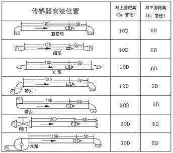
The sensor spacing is based on the inner edge of the distance between two sensors (see top view of sensor installation method). After entering the required parameters, check the number displayed in window 25 and make the sensor spacing conform to the data in window 25.
§ 2.4.2 Sensor installation methodThere are four installation methods for sensors. These four methods are V method, Z method, N method, and W method. Below are separate explanations. Generally, for small diameters (DN100~300mm), the V method can be used first; When the V method cannot detect the signal or the signal quality is poor, the Z method should be used. When measuring pipes with a diameter of DN300mm or more or cast iron pipes, the Z method should be preferred.
The W method and N method are less commonly used methods and are suitable for fine pipelines below DN50mm.
§ 2.4.2.1 V methodThe V-method is generally the standard installation method, easy to use, and accurate in measurement. The measurable diameter range is 25mm to large
About 400mm, recommended for use on pipelines ranging from 20 to 300mm. When installing sensors, pay attention to aligning the two sensors horizontally, with their centerlines aligned with the axis of the pipeline.

V method - side view

V method - sectional view
§ 2.4.2.2 Z methodWhen the pipeline is very thick or due to the presence of suspended solids in the liquid, thick scaling on the inner wall of the pipeline, or thick lining, resulting in weak V-method installation signal and machine malfunction, Z-method installation should be selected. as a result of; When using the Z method, ultrasonic waves are transmitted directly in the pipeline without refraction (known as single path), resulting in minimal signal attenuation.
The Z-method can measure pipe diameters ranging from 100mm to approximately 6000mm. For actual installation of flow meters, it is recommended to use the Z-method for pipelines over 300mm.
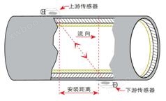
Z-method - side view

Z-method - sectional view
§ 2.4.2.3 W methodThe W method improves the measurement accuracy of small tubes by extending the ultrasonic transmission distance. Suitable for measuring small pipes below 50mm. When using the W method, the ultrasonic beam refracts three times inside the tube and passes through the fluid four times (four acoustic paths).

W method - side view

W method - sectional view
§ 2.4.2.4 N methodVery rarely used installation method.
§ 2.5 Power onPress the ON button to turn on the power of the flowmeter, and press the OFF button to turn off the power of the flowmeter.
After powering on the TDS-100P portable ultrasonic flowmeter, the self diagnostic program is first run to test the software and hardware,
If there is a fault, the corresponding error message will be displayed (see Chapter 5 Fault Analysis). After diagnosis, the machine will operate according to the parameters set by the user.
If the machine is already installed, it always enters the 01 display window after each power on. From the M01 window, it can be seen that the machine is adjusting the amplifier gain, and through this step, the flowmeter will find the optimal receiving working state. After the process prompts of 1, 2, and 3 are displayed in the upper left corner of the monitor, the machine automatically enters the normal measurement state, and the word "* R" is displayed in the upper left corner of the monitor.
Keyboard operation does not affect the measurement process, as the TDS-100P portable ultrasonic flowmeter adopts time-sharing technology for parallel processing internally. Measurement, calculation, typing, display, printing, serial port operation, input/output, etc. are all called "events", and each event is independent of each other. For example, modifying the date and time by the user will not affect anything unrelated to the date and time
Other tasks. The measurement process of the flowmeter is always carried out in the background of the user interface, so flow measurement will not stop due to window browsing. No matter which display window it is on, measurement, output and other tasks will continue as usual.
If it is being used ****** times or installed at a new installation point, the parameters of the new installation point need to be entered. Any parameters entered by the user are recorded in the NVRAM of the machine and will be stored for a long time until the user modifies them again.
When the user changes the parameters or moves the sensor, the machine will automatically recalculate and adjust according to the new parameters entered by the user.
 § 2.6 Keyboard
The keyboard of TDS-100P portable ultrasonic flowmeter is shown in the figure on the right, and the explanation is as follows:
0~9 and The key is used to input numbers or menu numbers;
The ◄ key is used to leave the grid or delete left characters;
The up and down keys ▲/+and ▼/- are used to enter the previous or next menu. When entering numbers, they are equivalent to positive and negative sign keys;
The MENU key (hereinafter referred to as the M key in text description) is used to access menus. First, type this key, then type the two digit key to enter the menu window corresponding to the number. For example, to enter the outer diameter of the tube, type MENU 1 1, where "11" is the address code of the tube outer diameter parameter window;
The enter key ENT, also known as the confirm key, is used to "confirm" the entered number or selected content. Another function is to press this key before entering parameters to enter the "modify" state.
The buzzer emits a "beep" sound, which can be turned off by selecting option 19 in window 77.
§ 2.7 How to operateThe TDS-100P portable ultrasonic flowmeter adopts a windowed software design, and all input parameters, instrument settings, and display measurement results are uniformly subdivided into more than 100 independent windows. Users can achieve the purpose of inputting parameters, modifying settings, or displaying measurement results by "accessing" specific windows. The windows are numbered with two digits (including+signs) from 00 to 99, followed by+0,+1, etc. Window number, also known as window address code, represents a specific meaning. For example, window 11 indicates the input of pipeline outer diameter parameters, window 25 displays the sensor installation distance, etc. See Chapter 4 for detailed window explanation.
The shortcut to accessing a window is to type the MENU key in any state, followed by typing the two digit window address
The code. For example, if you want to input or view the outer diameter parameters of the pipeline, the window address is 11, and you can type MENU 1 1.
Another method of accessing a window is mobile access, using the keys ▲/+, ▼/-, and ENT. For example, if the current window is 66, typing ▲/+will enter window 65, and then typing ▲/+will enter window 64; After typing ▼/-, return to window 65, and then type ▼/- to enter window 66.
The arrangement of window address codes follows a certain pattern (see the next section and the "Window Explanation" chapter), and users do not need to remember them one by one. They only need to remember the address codes of commonly used windows and the general location of infrequently used windows. Temporarily enter during use
Roughly adjacent windows, then use the ▲/+and ▼/- keys to find the window you want to access.
In short, the organic combination of shortcut methods and mobile methods can reveal that the operation method of accessing windows is actually both simple and convenient.
 The window itself is mainly divided into three types: (1) data type, such as M11, M12; (2) Select option type, such as M14; (3) Pure display type, such as M00, M01.
Access the data window to view the corresponding parameters. If you want to modify the numerical value, you can directly type the numerical key and press back
Car ENT, you can also enter the Enter key ENT, then enter the number keys, and then enter ENT to confirm.
For example, to input the outer diameter parameter of the pipeline as 219.2345, press the following button: MENU 1 1 to enter window 11, where the displayed value is the value entered last time. At this time, type the ENT key to display ">" and a flashing cursor on the left end of the second line of the screen, and enter the numerical parameter; You can also type the number keys directly without typing the ENT key, as follows:
1. Stainless steel
' src=' http://img78.mtnets.com/5/20210107/637456138772837850901.jpg ' width='135' align='left' height='57'> 2 1 9 . 2 3 4 5 ENT
Access the selection window to view the corresponding selection options. If you want to make modifications, you must first type the Enter key ENT. At this time, a ">" and flashing cursor will appear on the left side of the screen, indicating that you have entered the modifiable selection state.
Users can use the ▲/+and ▼/- keys to remove the desired selection, and then type the ENT key to confirm; You can also directly enter the selection item corresponding to the number and press the ENT key to confirm. For example, if the material of the pipeline is stainless steel, type MENU 1 4 to enter window 14, type ENT to enter the modification state. At this point, you can use the ▲/+and ▼/- keys to move out of "1 Stainless steel "option, enter ENT key to confirm; You can also directly enter the number key 1 in the modified state, and the second line of the screen will display "1 Stainless steel "Enter the ENT key to confirm.
In general, if you want to perform a "modify" operation, you must first type the ENT key (numeric windows can be omitted),
If the situation occurs where the ENT key cannot enter the modification state after typing, it means that the parameters have been fixed. Curing parameter function
Located in window 26, for applications where pipeline parameters are frequently changed, users should choose the "0. Save parameters with battery" option.
If the machine does not respond after pressing the key, it means that the keyboard has been "locked". The keyboard lock function is located in window 47. One way to unlock the keyboard is to enter the password for the lock operation. The user must enter the original password in this window before making any changes.
§ 2.8 Window Introduction
The windows are arranged according to the following rules:
Windows 00~09 are display windows that can display instantaneous flow rate, positive cumulative flow rate, negative cumulative flow rate, net cumulative flow rate, instantaneous flow rate, date and time, analog input current quantity, current working status, and today's flow rate.
Windows 10-29 are the initial parameter operation windows, where parameters such as pipe outer diameter, pipe wall thickness, fluid type, sensor type, sensor installation method, etc. are entered, and installation distance is displayed.
Windows 30-38 are the flow unit selection and accumulator option operation windows. In these windows, you can choose the working unit system, select the flowmeter working unit such as cubic meter, liter, etc., and open or close each accumulator or perform a "reset" operation on it.
Windows 40-49 include the traffic correction operation window, network identification address code (46), password protection (47), etc.
Windows 50-89 include settings and operations for printer output, RS-485 output, relay output, current loop output, batch controller, date and time, frequency signal output, alarm output, analog input, day month year accumulator, and other functions.
Windows 90-94 are flow meter inspection windows. Window 90 displays the signal strength and signal quality Q value; Window 91 displays the signal transmission time ratio; Window 92 displays the estimated fluid velocity through measurement; Window 93 displays the total time and time difference of the measured signal transmission; Window 94 displays the Reynolds number and instrument automatic correction factor.
There is no "window" to enter from 96 to 99. They represent print commands: M96 is used for printer paper feeding or loading, M99 prints the current window content.
+Windows 0~+9 are additional frequently used function windows, including power on/off time recording, total working time, total power on times, etc. It even includes a single precision function calculator.
There are also some windows related to hardware debugging operations, which are only used for manufacturer debugging. For detailed instructions, please refer to the "How to Use" and "Window Explanation" sections. If you still feel that the operation is difficult, please practice following the steps of inputting pipeline parameters in the next section.§ 2.9 Quick input of pipeline parameters and steps
The TDS-100P portable ultrasonic flowmeter requires the following parameters to be inputted for routine measurement:
1. Outer diameter of pipeline (M11)
2. Pipe wall thickness (M12)
3. Pipe material (M14)
4. Lining material parameters (if any, including lining material sound velocity M17 and lining thickness M18)
5. Fluid type (M20)
6. Sensor type (M23)
7. Sensor installation method (M24)
The input steps for the above parameter conditions generally follow the following setting steps:
1. Enter MENU 1 to enter window 11. Enter the outer diameter of the tube and press the ENT key
2. Type ▼/- to enter window 12, enter the pipe wall thickness, and then type the ENT key
3. Type ▼/- to enter window 14 ENT, ▲/+or ▼/- select the pipe and type the ENT key
4. Type ▼/- to enter window 16 ENT, ▲/+or ▼/- select the lining material and type the ENT key
5. Type ▼/- to enter window 20 ENT, ▲/+or ▼/- select the fluid type and type the ENT key
6. Type ▼/- to enter window 23 ENT, ▲/+or ▼/- select sensor type and type ENT key
7. Type ▼/- to enter window 24 ENT, ▲/+or ▼/- select the installation method, and then type the ENT key
8. Type ▼/- to enter window 25, and install the sensor according to the displayed installation distance and the installation method selected in the previous step (see the installation section in this chapter)
9. Enter MENU 0 1 to enter window 01 and display the measurement results
§ 2.10 How to determine if the sensor is working properly
Installation inspection refers to checking whether the sensor installation is appropriate, whether it can receive correct, strong enough ultrasonic signals that can make the machine work normally, to ensure the long-term reliable operation of the machine. By checking the received signal strength (M90), transmission time ratio (M91), and total transmission time and time difference (M93), it can be determined whether the installation is optimal.
The quality of installation directly affects the accuracy of flow values and the long-term reliable operation of the machine. Although in most cases, simply coating the sensor with coupling agent and attaching it to the outside of the pipe wall can obtain measurement results, the following checks should still be carried out to ensure good measurement results and reliable long-term operation of the instrument.§ 2.10.1 Signal strength
Signal strength (displayed in M90) refers to the strength of the received signal in both upstream and downstream directions. TDS-100P uses numbers from 00 to 99.9 to represent relative signal strength. 00.0 means no signal received; 99.9 represents * * * high signal strength.
In general, the stronger the signal strength, the more stable and reliable the measured values are, and the more reliable the operation can be for a long time.
During installation, the position of the sensor should be adjusted as much as possible and the coupling agent should be checked to ensure sufficient signal strength.
The condition for the system to function properly is that the signal strength in both directions is greater than 60.0. When the signal strength is too low, the installation position, spacing, and pipeline suitability of the sensor should be rechecked or replaced with Z-method installation.§ 2.10.2 Signal Quality (Q-value)
Signal quality, abbreviated as Q value (displayed in M90), refers to the quality of the received signal. Use numbers from 00 to 99 to indicate signal quality. 00 represents signal * * * difference; 99 indicates that the signal is * * * good.
The reasons for poor signal quality may be incorrect working parameters, high interference, poor sensor installation, or the use of poor quality, non specialized signal cables. In general, the sensor should be repeatedly adjusted to check if the coupling agent is sufficient until the signal quality is maximized.§ 2.10.3 Transmission Time Ratio
The transmission time ratio is used to confirm whether the sensor installation spacing is correct. The transmission ratio should be 100 ± 3 when installed correctly. The transmission time ratio can be viewed in M91.
When the transmission ratio exceeds the range of 100 ± 3, it is necessary to check whether the input parameters (pipe outer diameter, wall thickness, pipe material, lining, etc.) are correct, whether the installation distance of the sensor is consistent with the data displayed in M25, whether the sensor is installed on the same straight line as the pipeline axis, whether there is too thick scaling, and whether the pipeline at the installation point is deformed.§ 2.10.4 Total transmission time and time difference
The "total transmission time and time difference" displayed in M93 can reflect whether the installation is appropriate, because the internal measurement calculation of the flowmeter is based on these two parameters. Therefore, when the "time difference" reading fluctuates too much, the displayed flow rate and velocity will also jump sharply. This situation indicates poor signal quality, which may be due to poor pipeline conditions, inappropriate sensor installation, or incorrect parameter input. Under normal circumstances, the fluctuation of time difference should be less than ± 20%. But when the pipe diameter is too small or the flow rate is very low, the fluctuation of time difference may be slightly larger.
§ 2.10.5 Inspection items after installation
1) Check the pipeline parameters and confirm if everything is correct. Record the flow meter serial number and other parameters, and archive them together with signal strength and other status information for inspection.
2) Check the M90 menu to determine if the signal strength and Q value are greater than 70;
3) Check the M91 menu to see if the signal transmission ratio is between 97 and 103;
4) Check if the current date and time in the M60 menu are correct. If they are not correct, adjustments must be made. Otherwise, the day month year accumulation function and the power on/off function will not work properly;
5) For fixed application scenarios, use the M26 menu to select option 1 to solidify the backup of the currently entered parameters and settings, ensuring that the working parameters are not lost in case of power failure or depletion of the backup battery.
III How to determine if the flow meter is working properly when operating § 3.1
Type MENU 0 8. If the window displays "* R", it means it is working properly. In this window display, if there is an "E" symbol, it indicates that the current loop output exceeds the range by 100%, which is related to the setting of window 56. By increasing the input value in window 56, the letter "E" will no longer be displayed; If a current loop is not used, it can be ignored.
If there is a "Q" symbol, it indicates that the frequency output exceeds the range by 120%, which is related to the settings of windows 66-69. By increasing the input value in window 69, the word 'Q' will no longer be displayed; If frequency output is not used, it can be ignored.
If there is an "H" symbol, it indicates poor reception of ultrasonic signals. The handling method can be found in the chapter "Fault Analysis".
If there is a "G" symbol indicating that the instrument is performing automatic gain adjustment before measurement, it is generally normal. Only when it remains in this state for a long time, does it indicate that the machine is not functioning properly.
'I' indicates that ultrasonic signals cannot be received. Check if the sensor wiring is connected correctly and if the sensor is secure.
J "indicates that there is a hardware malfunction in the instrument, and the manufacturer can be contacted. The hardware malfunction may be temporary, please try powering it on again. Please refer to the chapter "Fault Analysis" for details.How to identify the flow direction of fluid in a pipeline
******Step: Confirm that the flow meter is working properly.
Step 2: Assuming that the sensor connected to the upstream wiring of the flowmeter motherboard is sensor A, and the sensor connected to the downstream wiring is sensor B.
Step 3: Check whether the instantaneous flow value is a "+" value ("+" is not displayed) or a "-" value; If it is "+", it indicates that the flow direction of the fluid is A → B; if it is "-", it indicates that the flow direction of the fluid is B → A.§ 3.3 How to choose a flow unit system
Using window 30, you can choose between metric or imperial flow unit systems: option 0 represents metric, option 1 represents imperial.
Usage: Type MENU 3 0 ENT and display '>' on the bottom left side of the screen to enter the selection state. Use ▼/- or ▲/+to select the desired option, and then type ENT to confirm.
§ 3.4 How to choose instantaneous flow units and cumulative flow units
Select instantaneous flow unit using window 31: First, enter MENU 3 1 to enter window 31, then enter ENT. The ">" will be displayed on the bottom left side of the screen to enter the selection state. Use ▲/+or ▼/- to select the desired flow unit, enter ENT to enter the selection time unit state, just like selecting flow units. Use the up and down keys ▲/+or ▼/- to select the desired time unit, and enter ENT to confirm.
Use window 32 to select the cumulative flow unit, using the same method as above. The selected unit is valid for positive, negative, and net accumulators.How to choose the multiplier factor of the accumulator in Section 3.5
The multiplication factor is used to expand the representation range of the accumulator, and window 33 is used for selection. The selected multiplication factor is effective for positive, negative, and net accumulators.§ 3.6 How to open or close a traffic accumulator
Window 34 can be used to open or close the traffic net accumulator; Window 35 can be used to open or close the positive flow accumulator; The negative flow accumulator can be opened or closed using window 36. Selecting 'YES' indicates opening the accumulator, while selecting' NO 'indicates closing the accumulator.
Users can choose to use positive, negative, and net cumulative traffic according to their needs for traffic data statistics.How to achieve zero clearing of traffic accumulator in § 3.7
Use window 37 to select the accumulator you want to reset to zero. Except for initial installation, this feature is generally not used.§ 3.8 How to restore factory settings
Type MENU 3 7, enter window 37 and type Press the ◄ key to restore all factory settings. But user calibration coefficients, network addresses, and other items will retain the values entered by the user.§ 3.9 How to use dampers to stabilize flow display
The function of a damper is to stabilize the flow display, and its essence is a filter that inputs a time constant in window 40. The larger the constant, the more stable it is. But when it is too large, it can cause measurement display lag and sluggish numerical display, especially when the actual flow rate changes dramatically, resulting in the displayed flow rate value not being able to follow the actual flow rate changes in a timely manner. So in general, this value is taken as the smaller one
The value is usually taken as 15-30 seconds.
This window belongs to the data type input window. The operation method is: after entering this window, directly enter the time constant, and then press the ENT key to confirm.§ 3.10 How to use zero point resection to avoid ineffective accumulation
The data in window 40 is called the low flow rate cutoff value, and the system treats flow rates with flow rates ***** values lower than this value as "0". This parameter can be set to avoid false accumulation of measurement errors caused by the flow meter when the actual flow rate is "0". Generally, this parameter is set to 0.03m/s.
When the flow rate is greater than the low flow rate cut-off value, the low flow rate cut-off value is independent of the measurement result and does not affect the measurement result in any way.§ 3.11 Setting Zero Point to Improve Measurement Accuracy
When measuring as "0", various measuring instruments will generate a "zero point", but the displayed measurement value is not equal to "0", and this value is called the "zero point". For any measuring instrument, the smaller the zero point it exists, the better. On the contrary, if the zero point of an instrument is too large, it indicates that its internal quality is poor.
If the zero point is not "0", measurement errors will occur. And the smaller the measured physical quantity, the greater the error caused by the zero point. Only when the zero point is small enough compared to the measured physical quantity, can the error caused by the zero point be ignored.
For ultrasonic flow meters, when the flow rate is low, the error caused by zero point cannot be ignored. Zero point setting is required to improve the accuracy of small flow measurement.
Enter MENU 4 2 to confirm that the fluid is indeed in a static state and the flow meter is in normal working condition. Enter ENT and wait for the process counter in the bottom right corner of the screen to decrease to "00", completing the static zeroing. The instrument will automatically enter window 01 to display the operation result. If a significant zero point is found, indicating a high flow velocity, repeat the 'zero setting' process.§ 3.12 Modify instrument coefficients (scale factors) for calibration and correction
The instrument coefficient refers to the ratio between the true value and the indicated value. For example, when the measured physical quantity is 2.00 and the instrument displays 1.98, the instrument coefficient is 2/1.98. The coefficient of the visible instrument is always 1. But when the instruments are mass-produced, it is difficult to achieve a coefficient of "1" for each instrument. The degree of difference or inconsistency is called the "consistency" of the instrument. High quality products are bound to have good consistency.
The TDS-100P portable ultrasonic flowmeter has an instrument coefficient of "1" when it leaves the factory, because in the design, it has achieved the goal of
The instrument coefficient is only determined by the frequency of the crystal oscillator and the sensor, and is independent of other circuit parameters. So the default values for instrument coefficients when leaving the factory are all "1".
Enter the ratio of true value to displayed value in M45 to complete the correction.
However, due to differences in factors such as pipelines during use, an "instrument coefficient" may also be generated, which is set to correct errors caused by different pipelines. The instrument coefficient must be input based on the actual calibration results.§ 3.13 Password protection (locking and unlocking)
After the instrument is locked, all menus can be viewed, but no modification operations can be made to avoid unrelated personnel making mistakes.
When adding a lock, type MENU 4 7 ENT, use ▲/+or ▼/- to select "Lock", type ENT, enter a 1-4 digit password, and type ENT to confirm.
When unlocking, only the correct password can be entered to open. First, type MENU 4 7 ENT, use the up and down keys ▲/+or ▼/- to select "Unlock", type ENT, enter the correct password, and type ENT to confirm.
Please remember your password. If you forget your password, please make sure to contact the manufacturer.§ 3.14 How to use a printer
The TDS-100P portable ultrasonic flowmeter supports instant printing and timed printing.
Instant printing includes M99 current window printing command, M98 diagnostic parameter printing command, and M97 pipeline parameter printing command. For example, typing MENU 9 9 will print the current window content. MENU 9 6 is the paper feeding command for the printer. After printing is completed, this command can be operated to facilitate tearing off the printing paper.
Timer printing can set the initial time, printing interval, printing duration, and printing content.
Select the printing content in window M50. First select "Open" the printer, then select the printed content in order (a total of 22 items). Type ENT for the content to be printed, then select "ON", and select "OFF" for the content not to be printed.
Enter the printing time in window 51. Refer to the explanation of windows 50 and 51 in Chapter 4 "Menu Window Detailed Explanation".
Select '0 output to internal serial bus' and' 1 output to serial port (RS-485) 'in the M52 window.How to modify date and time in Section 3.15
The date and time generally do not need to be modified. Because the flowmeter adopts the perpetual calendar clock chip produced by RAMTRON, it has high reliability. Even after an external power outage, the perpetual calendar can continue to operate for up to 5 years with the backup battery.
If you need to make modifications, enter the window MENU 6 0, type ENT, and the '>' will be displayed on the bottom left side of the screen to enter the modification state, which can be used Move the numbers that do not need to be modified and type ENT to confirm.How to adjust LCD display in Section 3.16
The backlight and contrast of LCD displays can be controlled through windows.
Use window M70 for backlight control. Type MENU 7 0, type ENT to display '>' on the bottom left side of the screen to enter modification mode, use ▲/+or ▼/- to select 'always on' to indicate that the backlight is always on; Select 'normally closed' to indicate that the backlight is always turned off; Select 'Press button to light up', then enter the lighting time of 'n' seconds, which means that the backlight will continue to light up for 'n' seconds after pressing the button and then automatically turn off.
Use window M71 to control the contrast of the LCD display. When the handwriting on the monitor is unclear or the viewing angle is not correct, the contrast needs to be adjusted. Type MENU 7 1 and type ENT. Display '>' on the bottom left side of the screen to enter modification mode. Use ▲/+or ▼/- to increase or decrease the contrast value, observe the screen display until satisfied, and then type Enter ENT to confirm.How to use RS-485 communication interface in Section 3.17
 The flow meter can be easily connected to the 485 bus using the matching RS-485 device. The conversion device is electrically isolated, making it easy to apply in industrial environments. RS-485 to RS-232 interface can also be used to connect with a computer for communication or software upgrades.
How to view daily, monthly, and annual traffic in Section 3.18
Use window M82 to view historical traffic data and machine operating status for the past 128 days.3After typing MENU 8 2 and selecting the 0th sub item "View by Day", the text will appear as shown on the right, with "000" in the upper left corner indicating the operation number; The "00-07-21" in the middle represents the date, and the "-------" in the upper right corner indicates the working status. If the status bar only displays "-------", it means that the machine is working completely normally during the working day. If other characters appear, please refer to the error code description. The following value is 3412.53 meters
Indicates the net cumulative traffic for the entire workday.
Check monthly traffic, type MENU 8 2 and select the first sub item "View by Month" option.
Check the annual traffic, type MENU 8 2 and select the second sub item "View by Year" option.How to achieve automatic flow replenishment during power outage periods in § 3.19
Select the "ON" option in window M83, and any lost data during the subsequent power outage period will be automatically restored upon power up
Add it to the flow accumulator. Select the 'OFF' option, this function will be disabled.
The use of this feature is essentially limited by many conditions and often cannot work reliably, so it is not recommended for users to use. Users should try to ensure uninterrupted power supply to the flowmeter to ensure the accuracy of measurement data.How to use the work timer in Section 3.20
Window M72 displays the time the instrument has been working since the last reset operation.
After typing ENT, select the "Yes" option to "reset" the work timer.§ 3.21 How to use a manual accumulator
Type MENU 3 8 ENT to start accumulating manually, type ENT to stop.§ 3.22 Viewing electronic serial numbers and other details
The TDS-100P portable ultrasonic flowmeter uses an electronic serial number (ESN) of * * * to distinguish each flowmeter, making it easy for manufacturers and users to manage. The ESN number is 138XXXXX, with 8 indicating production in 2008, 13 indicating the thirteenth edition, and XXXXX being a 5-digit serial number.
Use window M61 to check ESN, machine type, and version number.
The window M+1 can be used to view the total working time since the flowmeter was manufactured.
Using window M+4, you can view the total number of power on and off cycles since the flowmeter was manufactured.
|
4 Detailed explanation of menu window |
Menu window number |
|
Function |
M00 |
|
Display instantaneous flow and net cumulative amount |
M01 |
|
Display instantaneous flow rate and instantaneous flow velocity |
M02 |
|
Display instantaneous flow rate and positive cumulative amount |
M03 |
|
Display instantaneous flow rate and negative cumulative amount |
M04 |
|
Display date and time, instantaneous flow rate |
M05 |
|
Display heat flow rate and net heat |
M06 |
|
Display temperature input T1, T2 |
M07 |
|
Display analog inputs AI3 and AI4 |
M08 |
|
Display system error codes |
M09 |
|
Display today's net cumulative traffic |
M10 |
|
Enter the outer circumference of the tested pipeline |
M11 Enter the outer diameter of the tested pipeline |
|
The allowed numerical range for input is 0-6000mm |
M12 |
|
Enter the wall thickness of the tested pipeline |
M13 |
|
Enter the inner diameter of the tested pipeline (once the outer diameter and wall thickness are entered correctly, the inner diameter size will be automatically calculated, and this window can be skipped) |
M14 Select the material type of the tested pipeline The following pipeline materials are commonly used and users do not need to input their sound velocity: |
|
(0) Carbon steel (1) Stainless steel (2) Cast iron (3) Ductile iron (4) Copper (5) PVC (6) Aluminum (7) Asbestos (8) Fiberglass (9) Other |
M15 |
|
Used to input the sound velocity of pipes made of uncommon materials |
M16 Select the lining material type. If the pipeline does not have lining, please choose "unlined" The common lining materials are as follows, and users do not need to input their sound speed: (1) Epoxy asphalt (2) Rubber (3) Mortar (4) Polypropylene (5) Polystyrene (6) Polystyrene (7) Polyester (8) Polyethylene (9) Hard rubber, laminated wood |
|
(10) Polytetrafluoroethylene |
M17 |
|
Used to input the sound speed of lining made of uncommon materials |
M18 |
|
Enter the lining thickness of the lined pipeline |
M19 |
|
Input the roughness coefficient of the inner wall of the pipeline |
M20 Select fluid type The common fluids are as follows, and users do not need to input their sound velocity: (0) Water (1) Seawater (2) Kerosene (3) Gasoline (4) Fuel Oil (5) Crude Oil (6) Propane (-45 degrees) (7) 0 degrees butane (8) others (9) diesel (10) castor oil (11) Peanut oil (12) 90 octane gasoline (13) 93 octane gasoline (14) alcohol |
|
(15) 125 degree high temperature water |
M21 |
|
Used to input the sound velocity of uncommon fluids |
M22 |
|
Used to input the viscosity coefficient of uncommon fluids |
M23 Select the sensor configured locally There are 22 types of sensors to choose from: If the user provided sensor is selected, four parameters of the sensor need to be entered |
|
If a π - type pipe segment sensor is selected, three parameters of the sensor need to be input |
M24 There are four methods to choose from for installing sensors: |
|
(0) V-method installation (1) Z-method installation (2) N-method installation (3) W-method installation |
M25 |
|
Display the installation distance of the sensor |
M26 |
|
Set default parameters for power on |
M27 |
|
Store or read pipeline parameters |
M28 |
|
Choose whether to maintain the correct data from the last time when the received signal deteriorates, with the factory setting set to "Yes" |
M29 |
|
Set air traffic control status |
M30 |
|
Choose the measurement unit system, set to "metric" at the factory, and the conversion between imperial and metric will not affect the accumulated units |
M31 Choose instantaneous flow units, the following units are available for selection:30. The abbreviation for cubic meter is (m ) 1. Liter (L) 2. US gallon (GAL) 3. Imperial Gallons (IGL) 4. US Megagallon (MGL) 5. Cubic Feet (CF) 6. American made oil drums (OB) 7. British Petroleum Barrel (IB) |
|
The time units include:/day,/hour,/minute,/second, which can be combined into 36 flow units |
M32 |
|
Select cumulative traffic unit |
M33 Select cumulative multiplication factor |
|
The selection range of multiplication factor is 0.001 to 10000 |
M34 |
|
Net accumulator switch |
M35 |
|
Positive accumulator switch |
M36 |
|
Negative accumulator switch |
M37 |
|
Accumulator reset and clear all setting parameters |
M38 |
|
Manual accumulator, press any key to start, press any key to stop |
M39 |
|
Select display language: Chinese or English |
M40 |
|
Enter the damping coefficient and set it within the range of 0-999 seconds. 0 seconds indicates no damping, the factory setting is 10 seconds |
M41 |
|
Low flow rate cut-off value to avoid ineffective measurement |
M42 |
|
Static zeroing, pay attention to completely stopping the liquid flow in the tested pipeline during use |
M43 |
|
Clear the static zero point and restore it to the original zero point at the factory |
M44 |
|
Manually set the zero offset value, usually set to zero |
M45 Scale factor instrument coefficient, correction coefficient, factory set coefficient is 1 |
|
The coefficient is 1 without real flow calibration |
M46 Enter the network identification address code, except for 13 (0DH, enter), 10 (0AH, line break), 42 (2AH), 38 |
|
Any integer other than 65535 is acceptable. Each flowmeter has an address code IDN for networking purposes |
M47 |
|
System lock, password protection to prevent parameter changes |
M48 |
|
Linearity Line Correction Data Input |
M49 |
|
View serial input content |
M50 |
|
Timed Print Output Options |
M51 |
|
Timed output time setting |
M52 Print data output flow control. If "0. Input to internal serial bus" is selected, the data will be sent to the printer |
|
If you choose "1 Output to serial port ", all recorded data is sent to RS-485 interface |
M53 |
|
Display analog input A15 |
M54 |
|
Display pulse output pulse width setting |
M55 |
|
Selection of current loop output mode |
M56 |
|
Corresponding value when the current loop outputs 4mA |
M57 |
|
Corresponding value when the current loop outputs 20mA |
M58 |
|
Current loop output inspection |
M59 |
|
Current output value of the current loop |
M60 |
|
Set date time |
M61 Flow meter software version number, electronic serial number of this flow meter |
|
Users can use this electronic serial number for device statistics and management |
M62 |
|
RS-232/RS-485 serial configuration |
M63 |
|
Communication protocol selection (including compatible protocol selection) |
M64 |
|
Analog input A13 corresponds to the range of measurement values |
M65 |
|
Analog input A14 corresponds to the range of measurement values |
M66 |
|
Analog input A15 corresponds to the range of measurement values |
M67 |
|
Set the frequency output signal frequency range, which is 0-9999Hz. The factory setting is 0-1000Hz |
M68 |
|
Set the frequency signal output lower limit flow rate |
M69 |
|
Set the frequency signal output upper limit flow rate |
M70 |
|
The backlight illumination time of LCD display, the input value represents how many seconds the backlight can be illuminated |
M71 |
|
LCD display contrast control, the smaller the input value, the dimmer the LCD display |
M72 |
|
The working time timer can be reset to zero by pressing the ENT key and selecting "YES". |
M73 |
|
Set the lower limit flow rate of alarm 1 #. This flowmeter is equipped with two alarm modes, and the user must also * * select the alarm output content in the M77 or M78 window |
M74 |
|
Set 1 alarm upper limit flow |
M75 |
|
Set 2 alarm lower limit flow rates |
M76 |
|
Set 2 alarm upper limit flow |
M77 Buzzer setting options |
|
By selecting the appropriate triggering event, the buzzer will emit a "beep" sound when the event occurs |
M78 Set OCT (open collector output) option |
|
By selecting the appropriate triggering event, the OCT circuit will be turned on when the event occurs |
M79 |
|
Set relay output options |
M80 |
|
Select quantitative (batch) controller control signal |
M81 |
|
Select quantitative (batch) controller |
M82 |
|
Daily, Monthly, and Annual Flow Accumulator |
M83 |
|
Automatic power-off flow switch |
M84 |
|
Select heat measurement unit |
M85 |
|
Select a heat measurement temperature source |
M86 |
|
Select heat capacity |
M87 |
|
Heat accumulator switch |
M88 |
|
Heat accumulator multiplication factor |
M89 |
|
Current temperature difference and sensitivity |
M90 |
|
Display signal strength and signal quality |
M91 |
|
The signal transmission time ratio should be within the range of 100 ± 3% if the parameters of the tested pipeline are input correctly and the sensor installation is appropriate. Otherwise, the input parameters and sensor installation should be checked |
M92 |
|
Estimate the sound velocity of the fluid. If this value differs significantly from the actual sound velocity of the fluid, it is necessary to check whether the input pipeline parameters and sensor installation are correct |
M93 |
|
Display total propagation time and propagation time difference |
M94 |
|
Display Reynolds number and its pipeline factor |
M95 |
|
Display positive and negative heat |
M96 |
|
Printer feed command |
M97 |
|
Print the parameters of the currently used pipeline |
M98 |
|
Print the current pipeline diagnostic signal |
M99 |
|
Print the current window content |
M+0 |
|
Display the last power outage time and flow rate |
M+1 |
|
Display the total working time of the flowmeter |
M+2 |
|
Display the last power outage time |
M+3 |
|
Display the flow rate during the last power outage |
M+4 |
|
Display the total number of times the flowmeter has been powered on |
M+5 |
|
Scientific calculator, convenient and applicable. Operators are selected rather than pressed directly |
M+6 Threshold setting for fluid sound velocity |


