-
E-mail
312534289@qq.com 467090947@qq.com
-
Phone
18761882890/13814089468
-
Address
15-20 Xingda Road, Nanjing Yangtze River Industrial Development Zone
Product Categories
- Ultrasonic water meter
- parshall flume
- Residual chlorine analyzer
- COD
- Electromagnetic Flowmeter
- CONDUCTIVITY METER
- Ultrasonic Heat meter
- Sludge concentration meter
- Ultrasonic Open Channel Flowmeter
- Ultrasonic level gauge
- PH meter
- ultrasonic flowmeter
- Dissolved oxygen analyzer
- doppler flow meter
- current meter
- Ultrasonic depth sounder
Nanjing Zhuoma Electromechanical Co., Ltd

Ultrasonic heat meter*********
NegotiableUpdate on 06/02
- Model
- Nature of the Manufacturer
- Producers
- Product Category
- Place of Origin
Overview
1、 Overview: Ultrasonic calorimeter is an instrument used to measure and display the heat released (absorbed) by a heat (cold) liquid flowing through a heat and cold exchange system. The ultrasonic heat meter consists of a controller and a base meter. The controller consists of a flow sensor, a microprocessor, and a paired temperature sensor. The microprocessor obtains flow signals through flow sensors and base meters, obtains outlet and inlet water temperature signals from temperature sensors, and calculates the energy exchanged by the system based on the standard heat calculation formula. Users can choose an ultrasonic heat meter with M-BUS communication function, which can
Product Details
>
1、 Overview
Ultrasonic calorimeter is an instrument used to measure and display the heat released (absorbed) by a heat (cold) liquid flowing through a heat and cold exchange system.
The ultrasonic heat meter consists of a controller and a base meter. The controller consists of a flow sensor, a microprocessor, and a paired temperature sensor. The microprocessor obtains flow signals through flow sensors and base meters, obtains outlet and inlet water temperature signals from temperature sensors, and calculates the energy exchanged by the system based on the standard heat calculation formula.
Users can choose an ultrasonic heat meter with M-BUS communication function, which can communicate with other devices through the M-BUS bus to form a remote meter reading management system; Ultrasonic heat meters with wireless communication capabilities can also be used, which can communicate through PDA or other wireless devices to form a remote meter reading management system; The management department can access the data in the table at any time to facilitate the control of users' heat consumption.
The ultrasonic heat meter is a high-performance, low-power electronic heat meter developed and designed with reference to European standards EN1434 and OIML-R75 international regulations. Complies with the CJ128-2007 "Heat Meter" product standard issued by the Ministry of Construction of China. M-BUS or wireless remote communication protocol complies with CJ/T128-2004.
2、 Characteristics
1. Low voltage alarm.
2. Automatic data correction technology.
3. Temperature sensor open circuit and short circuit alarm.
4. High definition wide temperature LCD display.
5. The flow is calibrated in 8 segments with high accuracy.
6. Ultra low power consumption (static power consumption less than 7uA).
7. The pipe section is a straight through integrated structure manufactured using forging technology.
8. The measuring mechanism has no moving parts, no wear and tear, and the measurement accuracy is not affected by the service life.
9. Equipped with photoelectric interface, communication distance of more than 2 meters, and infrared tools can be used to achieve meter reading.
10. Installation is extremely convenient, installed horizontally or vertically.
11. M-BUS or wireless remote communication can be used, with a long communication distance.
3、 Usage method
1. When there is flow, the heat meter will cycle and display:
Accumulated heat:accumulateXXX kWh
Accumulated traffic:accumulateXXX. XX meq \ \ o (\ \ s \ up 5 (3)\ \\ do 2()) 3
Instantaneous flow rate:instantaneousXxx.xxx m3/h
Temperature: XX. XEntrance and exitXX.X ℃
Temperature difference:Temperature differencex.x ℃
Accumulated working time:accumulateXXX h
2. When there is no flow, the heat meter often displays:
Accumulated heat:accumulateXXX kWh
3. M-bus communication
Users can choose M-bus communication function ultrasonic heat meters, which can be remotely read with collectors, concentrators, management software, etc. The collector has a carrying capacity of no less than 64 heat meters. Before use, an address file is established on the upper computer, and the table address is set at the factory (the 12 digit code of the ultrasonic heat meter production serial number ID). After the centralized meter reading system composed of the heat meter, concentrator, collector, upper computer, etc. is completed, the management department can read the data in the table at any time.
Note: 1. In a system, the address of the heat meter cannot be duplicated.
2. The M-BUS communication line of the heat meter does not distinguish between positive and negative poles, and can be connected to the collector interface through the M-BUS bus.
4. Data query
The ultrasonic heat meter stores the monthly usage heat and flow rate for the past 18 months. Gently shake the magnet near the production serial number of the ultrasonic heat meter, and the heat meter will display:
Version number: No.XXXX
Year, Month, Day: XX-XX-XX
Hour, minute, second: XX.XX.XX
Current time year and month:
XX-XXCurrent monthly heat usage:accumulate
XXX kWhCurrent monthly traffic usage:accumulate
XXX. XX meq \ \ o (\ \ s \ up 5 (3)\ \\ do 2()) 3
Last month year and month: XX-XXLast month's heat usage:accumulate
XXX kWhLast month's traffic usage:accumulate
XXX. XX meq \ \ o (\ \ s \ up 5 (3)\ \\ do 2()) 3
Last February Time Year/Month: XX-XXHeat usage in February:accumulate
XXX kWhLast February's usage of data:accumulate
XXX. XX meq \ \ o (\ \ s \ up 5 (3)\ \\ do 2()) 3
...... ......
Last 17 months Year and Month: XX-XXLast month's heat usage:accumulate
XXX kWhLast month's traffic usage:accumulate
XXX. XX meq \ \ o (\ \ s \ up 5 (3)\ \\ do 2()) 3
After 18 months of monthly heat usage, the monthly flow rate is displayed in a cyclic manner and enters a normal state for display.
4、 Work status
Due to the different resolution requirements and normal working conditions required for ultrasonic heat meters during calibration, our company's ultrasonic heat meters have two working states: calibration state and normal working state. The difference between the two working states is the display resolution.
The ultrasonic heat meter can be entered into the inspection state using the "inspection state startup card". Gently shake the left end of the transparent window of the "Check Status Start Card" against the production serial number of the ultrasonic heat meter, align the "Check Status Start Card" with the infrared interface of the ultrasonic heat meter, press the button, and the communication is successful. The heat meter enters the check status, and automatically enters the normal status after 4096S.
|
The specific list of differences is as follows: |
project |
Normal working condition |
|
Checklist status |
Small display unit for heat: |
1kWh |
|
0.001kWh |
* * * * Small display unit of accumulated traffic |
0.01meq \ \ o (\ \ \ \ up 5 (3)\ \s\\do |
2 ()) 3
|
0.00001 meq \ \ o (\ \ s \ up 5 (3)\ \s\\do |
2 ()) 3 |
5、 Technical parameters3flow sensor |
Nominal diameter3Common traffic (m) |
/h)3***Small traffic (m |
|
|
40 |
10 |
0.2 |
20 |
||
|
50 |
15 |
0.6 |
30 |
||
|
65 |
25 |
1 |
50 |
||
|
80 |
40 |
1.6 |
80 |
||
|
100 |
60 |
2.4 |
120 |
||
|
125 |
100 |
4 |
200 |
||
|
150 |
150 |
6 |
300 |
||
|
200 |
250 |
10 |
500 |
||
|
250 |
400 |
16 |
800 |
||
|
300 |
600 |
24 |
1200 |
||
|
/h) |
***Large traffic (m |
||||
|
/h) |
***Small display traffic |
||||
|
0.1meq \ \ o (\ \ \ \ up 5 (3)\ \\ do 2()) 3 (when in use) 0.00001meq |
\\O (\ \ s \ up 5 (3)\ \\ do 2()) 3 (during calibration) |
***Small display heat |
|||
|
1kWh (during use) 0.001kWh (during calibration) |
temperature sensor |
||||
|
***Small temperature difference |
1 or 3 ℃ |
||||
|
***Large temperature difference |
90℃ |
||||
|
***Small display temperature |
0.1℃ |
||||
|
Static working current |
< 7uA |
||||
|
Battery life |
>5 years9 LCD display number of digits |
||||
|
8 digits |
***Accumulated working hours94.2x10 |
||||
|
Hours (When working hours>hours, only the last 8 significant digits of * * * can be displayed) |
***Large cumulative traffic |
||||
|
4.2x10 |
Meq \ \ o (\ \ s \ up 5 (3)\ \\ \ do 2()) 3 (cumulative traffic>9999999.99 meq \ \ o (\ \ \ up 5 (3)\ \When displayed at 3 o'clock, only the last 8 significant digits of * * * can be displayed |
||||
|
accuracy class |
Level II or III |
||||
pressure resistance
|
1.6MPa |
pressure loss |
≤ 0.025 MPa |
|
|
6、 Error handling Error symbol meaning Reason for error processing method |
ERR5 |
ERR6 |
ERR7 |
ERR8
ERR9
Temperature measurement error
PT1000 disconnection, open circuit, etc
Check hardware
7、 Installation
1. Installation of the entire meter:
(1) Suggest installing a filter before the ultrasonic heat meter.
(2) It is recommended to install a valve before the filter to facilitate maintenance and cleaning of the filter.
(3) Before installation, please flush the pipeline to prevent any debris such as hemp fibers, sand, and stones inside.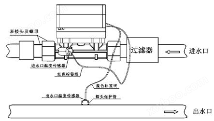
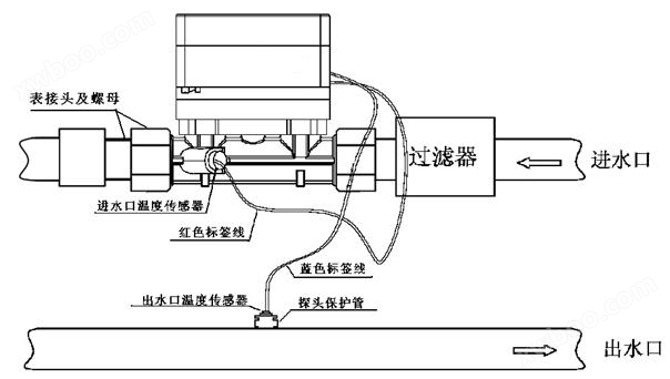
(4) Do not pull, rotate, or collide with the internal components of the pipeline during installation to avoid damaging the body.
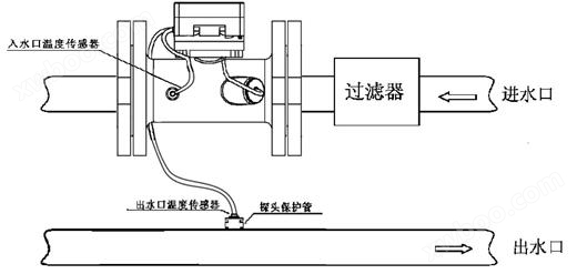 |
(5) During installation, sufficient maintenance space must be reserved and installed in the direction of the flow indication arrow on the pipe section.
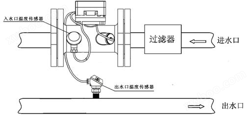 |
(6) The ultrasonic heat meter is installed horizontally or vertically at the inlet of the pipeline, but when installed horizontally, the two transducers should be on the same horizontal plane. When installed vertically, the ultrasonic heat meter must be installed on a straight pipeline with upward water flow.
(7) When connecting the body to the pipeline, do not apply too much force to avoid damaging the sealing gasket and causing water leakage.
(8) The heat meter should be handled with care and not bumped during transportation; Storage in strong electromagnetic fields should be avoided.
DN40 caliber
 |
 |
||
DN50、 65 caliber
DN80-300 caliber
Figure 1 Schematic diagram of overall installation of ultrasonic heat meter
Attention: During installation, install the temperature sensor connector labeled with the inlet probe in the ultrasonic waveform table.
2. Installation of temperature probe:
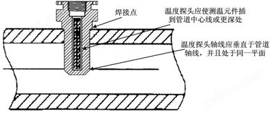
A. Installation method of DN40-65 caliber heat meter temperature probe:
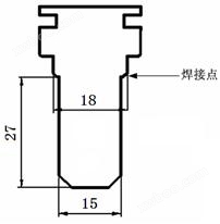
Figure 2
(1) The size of the probe protection tube is shown in Figure 2
 |
 |
||
(2) Drill a hole vertically downwards at an appropriate position in the outlet pipeline (hole diameter 15mm);
(3) After drilling the installation hole, place the probe protection tube in the corresponding position of the installation hole and weld it at the "welding point";
(4) After the welding is completed and the welding joint cools down, screw the outlet probe into the probe protection tube and screw it to the bottom;
|
(5) Seal the probe and probe protection tube with lead. |
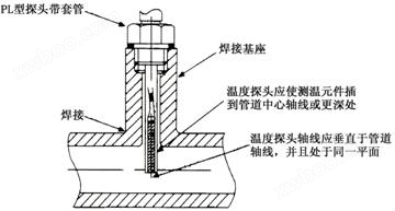
B. Installation method of DN80-300 caliber heat meter temperature probe: |
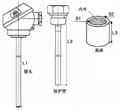
(1) Select the probe, protective tube, and welding base according to the pipe diameter, refer to the table below. |
Figure 3 |
||
|
Unit: mm |
pipe diameter |
Probe length L1 |
|||
|
Protection Manager L2 |
105 |
85 |
20 |
18 |
28 |
|
Welding base |
140 |
120 |
|||
Long L3
Inner diameter D1
Outer diameter D2
DN80~150
DN200~300
(2) Drill a hole vertically downwards at an appropriate position in the outlet pipeline (hole diameter 18mm);
(3) After drilling the installation hole, weld the base to the corresponding position of the installation hole;
(4) After the welding is completed and the welding joint cools down, cover the protective tube of the outlet probe with a sealed copper gasket, wrap the outer wire with adhesive tape, and screw it into the corresponding outlet pipe base, making sure to tighten it;
 |
 |
||
(5) Insert the probe into the bottom of the protective tube and secure it tightly with fixing screws.
|
(6) Seal the probe and probe protection tube with lead. |
Note: 1. When leaving the factory, the inlet probe protection tube has been installed on the body, only the outlet probe needs to be installed. |
2. When welding the base, the end with inner wire should face upwards, and the end without wire should be welded. |
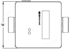
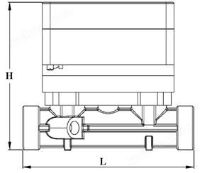
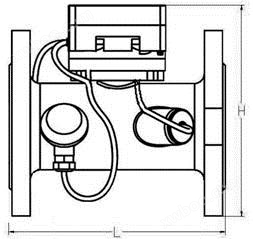
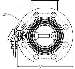
8、 Dimensions DN40 caliber dimensions |
Outline dimension drawing of base table with dimensions ranging from 50 to 200 |
|
40 |
200 |
100 |
135 |
Caliber (mm) |
|
50 |
200 |
165 |
190 |
Length L (mm) |
|
65 |
200 |
185 |
210 |
Width W (mm) |
|
80 |
225 |
200 |
220 |
Height H (mm) |
|
100 |
250 |
220 |
245 |
Connection method |
|
125 |
250 |
250 |
260 |
Thread G2B |
|
150 |
300 |
285 |
300 |
Flange ¢ 125-4 × ¢ 19 |
|
200 |
350 |
340 |
365 |
Flange ¢ 145-4 × ¢ 19 |
|
250 |
450 |
405 |
430 |
Flange ¢ 160-8 × ¢ 19 |
|
300 |
500 |
460 |
485 |
Flange ¢ 180-8 × ¢ 19 |
Flange ¢ 210-8 × ¢ 19
Flange ¢ 240-8 × ¢ 22
Flange ¢ 295-12 × ¢ 22
Flange ¢ 355-12 × ¢ 26
Flange ¢ 410-12 × ¢ 26
Note: The width in the above table is the self width of the ultrasonic base surface, and the width of the finished surface may be about 20-30mm wider than the base surface due to assembly differences.
9、 Supporting supply
1. One ultrasonic heat meter
2. 1 pair of temperature sensors


