-
E-mail
2880956079@qq.com
-
Phone
13524471462
-
Address
No. 253 Yulu Road, Jiading District, Shanghai
Ankerui Electric Co., Ltd
Analysis of the Application of Acrel-1000 Substation Integrated Automation System in the Renovation of a 66kV Substation in Yingkou
Date: 2025-11-26Read: 26
0. Introduction
Driven by the rapid development of society, the dependence of Chinese enterprises on electricity energy in production is gradually increasing, and the contradictions in electricity supply for production and daily life are even greater. In order to ensure sufficient electricity and energy supply in the production and daily life of enterprises, it is necessary to strengthen the management of substations, which can ensure more stable operation of substations and guarantee the supply of electricity and energy.
1. Current operation status of the substation
In recent years, the failure rate of traditional substations in China has been relatively high, which has greatly affected the lives of residents and the production of enterprises. This requires in-depth analysis of the failure problems and causes within the power system, and it is found that the main cause of the failure problems is equipment aging and inadequate maintenance. From the actual situation analysis, the faults that occur in traditional substations are relatively serious, difficult to maintain, and can lead to long-term power outages, greatly affecting the daily lives of urban residents and the production and operation of enterprises. At present, substations are mainly managed through unmanned substation mode, which has certain characteristics and does not require on duty personnel to complete real-time monitoring. Because modern substation equipment with high technological level is installed, only a small number of staff assistance is needed to complete the operation, and remote management and control can be achieved. For the unmanned management mode, the staff in the control center only need to use scientific means to timely detect problems in the operation of the substation and carry out maintenance and handling in a timely manner.
2. Advantages and Problems of Substation Integrated Automation System
2.1. System Advantages
Compared with the traditional secondary system of conventional substations, the comprehensive automation system of substations makes the operation and maintenance management of substations more convenient, safe and reliable, which can greatly improve the work efficiency of substations and promote the modernization development of the power grid system. With the development of computer technology, network technology, and communication technology, and the improvement of automation level, the secondary system of substations has basically achieved comprehensive automation of substations. Through the comprehensive automation system, relay protection can be self checked and mutually inspected, with functions such as fault recording, event recording, operation monitoring, and control, reducing operation and maintenance costs and improving the safe and reliable operation level of substations.
2.2. Existing problems
With the development of the power system, there are more and more substations, which leads to equipment failures. Based on the analysis of the location of the failures, according to the relevant data of the comprehensive automation system failures in the power grid substations in recent years, the station control layer has the highest number of failures, accounting for 45.39%; Next is the spacing layer, accounting for 30.50%; Next is the network layer, accounting for 12.76%; Finally, the remote control system accounts for 11.35%.
L station control layer malfunction
The main reasons for the majority of station control layer failures are hardware failures in the backend system, incorrect parameter settings in the backend system, and software failures in the front-end processor.
(1) The hardware failure of the backend system is manifested as frequent crashes of computer equipment. The main reason is that the device has been running for too long and has experienced a certain degree of aging, resulting in damage to the motherboard and hard drive. In addition, hardware devices such as displays in the backend system are also severely damaged.
(2) The parameter setting error in the backend system is manifested as unclear definition of message names, and inconsistency between the main and sub screen displays and the actual situation. Mainly due to the huge amount of information in the automation system, and the inadequate acceptance and transmission of new construction, renovation/expansion projects. In addition, non-standard message names are also the main reason for such defects.
(3) The main manifestations of front-end computer software failures are unexplained crashes and application crashes. Usually, it can be restored by restarting.
Interval layer fault
The equipment failure in the interlayer is mainly caused by two aspects. The most common issue in the interval layer is the secondary loop problem. The communication status cannot correspond well with the actual situation due to poor insulation points or inadequate auxiliary contacts after each operation of the equipment. Another issue is caused by the measurement and control device, manifested in hardware facilities, where communication interruptions often occur due to internal plugin or module problems. There are relatively few problems with the software of the measurement and control device, but the defects that occur are quite serious. If the scheduled values are lost and the on-site inspection is not in place, it is easy to cause operational accidents. There were also incidents of measurement and control devices crashing on site, causing remote control commands to be unable to execute and operate normally. Power off and restart the measurement and control devices to restore normal operation.
Network equipment malfunction
According to relevant information, the current network communication equipment problems are not too serious, but if they occur, they can lead to serious problems, which may cause interruptions in the data collection work of substations or substation equipment. So it is necessary to handle such faults in a timely manner. Analyzing and studying the causes of network equipment failures is often due to poor product quality, especially hardware issues with various network communication devices such as hubs and switches.
3. Acrel-1000 Substation Integrated Automation System Solution
3.1. Program Overview
The Acrel-1000 substation comprehensive automation monitoring system consists of two layers of equipment, namely the station control layer and the interval layer, in terms of logical functions, and is connected using a layered and open network system. The station control layer equipment includes a monitoring host, which provides a human-machine interface for station operation, realizes the management and control of equipment in the interval layer, forms a whole station monitoring, and communicates with remote monitoring and dispatch centers; The interval layer is composed of several secondary subsystems, which can independently complete the on-site monitoring function of interval layer equipment in the event of station control layer and station control layer network failure.
Based on the specific situation of the project, the design scheme has high reliability, easy scalability, and a friendly human-machine interface. The performance price ratio is high. The monitoring system consists of two parts: the station control layer and the interval layer, and adopts a layered distributed network structure. The station control layer network uses TCP/IP protocol Ethernet. The station control layer network adopts a single network dual machine hot standby configuration.
3.2. Intelligent transformation of substation comprehensive automation system
3.2.1. Reconstruction of station control layer issues
The station control layer adopts Acrel-1000 substation comprehensive automation system to achieve monitoring and management of power equipment. And integrate current domestic and foreign computer technology, network technology, communication technology, information processing technology, power distribution automation technology and other technologies to achieve functions such as telemetry, remote signaling, remote control, and remote adjustment. Meet all the requirements of users for the protection, monitoring, and power quality of the power system.
The Acrel-1000 substation comprehensive automation system adopts a single network dual machine hot standby configuration. Under normal circumstances, the host is in working state and the slave is in monitoring state. Once the slave detects an abnormality in the host, it will replace the host in a short time to achieve the functions of the host. At the same time, the system meets the following requirements:
The average time between station control layers (MTBF) is greater than or equal to 20000 hours, and the average time between interval level measurement and control devices is greater than or equal to 30000 hours;
The average CPU load rate of each workstation in the station control layer is: less than or equal to 30% during normal operation (within any 30 minutes), and less than or equal to 50% during power system failure (within 10 seconds);
Network average load rate: less than or equal to 20% during normal operation (within any 30 minutes), and less than or equal to 40% during power system failure (within 10 seconds);
3.2.2. Renovation of Interval Layer Issues
The AM5SE series microcomputer protection device can be configured in the substation distribution system. The AM5SE series microcomputer protection device has the following advantages, effectively balancing the economic benefits brought by the equipment with the technical content and quality issues of the product itself.
In terms of product design, the device has unified hardware, including power module, CPU module, input/output module, control circuit module, analog acquisition, communication module, etc; The overall design adopts a modular approach with strong universality, allowing for flexible configuration of protection functions for different primary equipment on the same hardware platform, achieving protection and measurement functions for substations and equipment with voltage levels of 35kV and below. This includes protection and automatic control functions for 35kV incoming lines/main transformers (generally with a capacity of 2000kVA or above)/PT/busbars, 10kV incoming lines/feeders/distribution transformers (generally with a capacity of 2000kVA or below)/high-voltage motors/high-voltage capacitors/busbars/PT and other equipment.
In terms of product quality, the device has obtained type test reports and electromagnetic compatibility inspection reports from the third-party type test of the National Relay Protection and Automation Equipment Quality Supervision and Testing Center. It has passed 10 electromagnetic compatibility testing certifications, including radiation emission limit test, conduction emission limit test, radio frequency electromagnetic field radiation immunity, electrostatic discharge immunity, radio frequency field induced conducted disturbance immunity, electrical fast transient pulse group immunity, slow damping oscillation wave immunity, surge immunity, power frequency magnetic field immunity, AC and DC voltage sag interruption. Among them, the fast transient, electrostatic discharge, and surge immunity performance all meet the requirements of level IV.
In terms of interface resources, the device has 12 analog channels, which can be selected as input for protection current, measurement current, and voltage; The AC voltage input port should be able to connect phase voltage, as well as connect voltage, zero sequence voltage, or unbalanced voltage, and adapt to various PT connection methods. The protection current and measurement current channels can be connected to three-phase current separately; The other two AC current channels can be connected to zero sequence current, unbalanced current, or line current. It has zero sequence current and zero sequence voltage measurement functions, and cooperates with the power monitoring system to achieve small current grounding line selection function.
3.2.3. Data communication problem transformation
The comprehensive automation system of the substation requires centralized analysis and management of equipment information within the station. Due to interface issues between different system unit devices and products, we have converted the communication interfaces of each system unit device into open and unified interface standards through protocol conversion devices, allowing users to choose the appropriate interface according to their own needs.
4. System functions
4.1. real-time monitoring
The Acrel-1000 substation comprehensive automation system visually displays the operating status of distribution lines in the form of a distribution primary diagram, monitors real-time electrical parameter information such as voltage, current, power, and power factor of each circuit, dynamically monitors the closing and opening status of circuit breakers, isolating switches, ground knives, and related fault, alarm, and other signals of each distribution circuit.

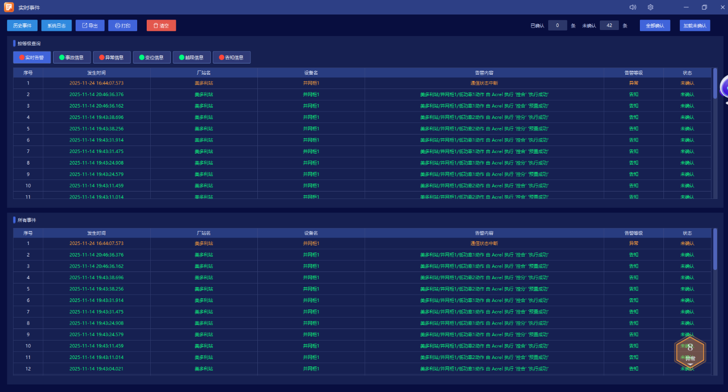
4.2. Alarm Handling
The monitoring system has an accident alarm function. Accident alarm includes circuit breaker tripping and protection device action signals caused by abnormal operation; Pre warning alarms include general equipment displacement, abnormal status information, analog or temperature exceeding limits, etc.
1) Accident alarm. When in the accident state mode, the accident alarm immediately emits an audible alarm (the alarm volume can be adjusted arbitrarily), and the display screen of the operator workstation changes color and flashes to indicate that the device has changed position. At the same time, a pop-up window displays a red alarm text. The alarm is divided into real-time alarm and historical alarm, and the historical alarm text has the function of selecting, querying, and printing.
2) For each measurement value (including calculated values), four specified operating limits (physical lower limit, alarm lower limit, alarm upper limit, physical upper limit) are set by the user sequence and defined as pre alarm and accident alarm, respectively.
3) The alarm methods have various forms of expression, including pop ups, flashing screens, etc., but not limited to the above methods. Users can add or modify alarm information according to their own needs.
4.3. Regulation and Control
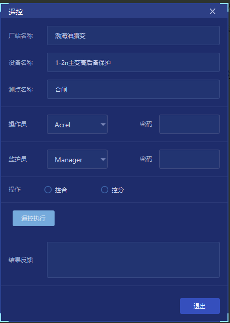
The operator controls the electrical equipment that needs to be controlled. The monitoring system has operation monitoring function, allowing monitoring personnel to implement monitoring on the operator workstation to avoid misoperation.
The operation control is divided into four levels:
Level control, on-site maintenance control of equipment. Control with priority. When the operator places the remote/local switch of the local equipment in the local position, all other control functions will be locked and only on-site operations will be carried out.
Second level control, backup control for the interval layer. The switching between it and the third level control is completed in the interval layer.
Third level control, station control layer control. This level of control is completed on the operator workstation and has the ability to switch between remote/station control layers.
Fourth level control, remote control, priority.
In principle, interval level control and equipment on-site control are used as backup or maintenance operation methods. To prevent misoperation, step-by-step operation is required under any control mode, including selection, returning to school, and execution. Operator and supervisor passwords and line codes should be set at the station level to ensure the safety and correctness of the operation. For any operation method, ensure that the next step is only performed after the previous operation step is completed. Only one control method is allowed to be effective at a time.
The equipment included in the control includes: 35kV and below circuit breakers; 35 kV and below isolating switches and grounding switches with live moving mechanisms; Station power 380V circuit breaker; Main transformer tap; Remote reset and remote switching connection piece of relay protection device.
5. Acrel-1000 Substation Integrated Automation System Renovation Plan
5.1. System Architecture
The substation of this project is connected to the power grid through a 66kV single circuit mains power input single busbar, and is stepped down to 10kV by a 12500kVA main transformer for various circuit distribution within the station.

5.2. Equipment selection
The substation renovation of this project mainly focuses on the renovation of the main transformer protection, the secondary 10kV switchgear in the station, and the monitoring system backend. The small current grounding line selection device cannot be replaced immediately, so this renovation will utilize the old equipment.
The main transformer protection panel cabinet is located in the electrical monitoring room, and is equipped with one differential protection device AM5SE-D2, one high backup protection device AM5SE-TB, one low backup protection device AM5SE-TB, one non electric protection device AM5SE-FD, one high side measurement and control device AM5SE-K, one low side measurement and control device AM5SE-K, one transformer temperature controller ARTM-8, and other control equipment such as transfer switches, pressure plates, and air switches.
The line protection screen is divided into two cabinets according to the 10kV segmentation principle. On the 1 # 10kV line protection measurement and control screen, there are four line protection AM5SE-F, and on the 2 # 10kV line protection measurement and control screen, there are four line protection AM5SE-F and one used small current grounding line selection device.
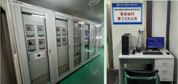
The monitoring host is configured according to the single network dual machine scheme, with one monitoring host screen installed in the station and one operation console installed in the duty room. Under normal circumstances, the host is in working state and the slave is in monitoring state. Once the slave detects an abnormality in the host, it will replace the host in a short period of time to achieve the functions of the host.

5.3. On site comparison before and after renovation
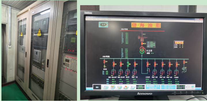
The power outage time for the substation renovation of this project is only 24 hours. The secondary cables of the microcomputer protection group cabinet for this renovation were sorted out according to the original secondary drawings, considering cable laying. During the design phase, the position of the back terminal was kept unchanged, and only the internal wiring of the device to the cabinet was adjusted. At the same time, the position of the switch and pressure plate was installed near the side of the device according to the original site design.
The on-site situation before and after the renovation is shown in the following figure. During the design phase of this renovation, the original drawings were strictly followed, considering the convenience of construction. During the construction phase, the cables were sorted and point-to-point according to the construction specifications, and remote control tests were conducted on the high and low voltage circuits of the main transformer and the 10kV outgoing circuits on site. The renovation and power transmission were successfully completed within 24 hours.
The comprehensive automation renovation project of substations is an old substation renovation project. Through the comprehensive automation renovation of substations, real-time and unified substation data and dispatch room data can be achieved, making remote control more accurate. Each signal data can be stored in the substation comprehensive automation system, so that in the future, when the power grid fails, real-time transmission data and past action signals can be called for analysis, bringing convenience to accident signal judgment.