-
E-mail
2880956079@qq.com
-
Phone
13524471462
-
Address
No. 253 Yulu Road, Jiading District, Shanghai
Ankerui Electric Co., Ltd
The photovoltaic energy storage and charging system is self used, and by using the energy storage system to cut peak and fill valley, the stability of the system's power supply can be improved
Date: 2025-10-30Read: 26
Introduction
With the rapid development of renewable energy utilization technology, the installed capacity of distributed energy generation equipment in China has grown rapidly. Among them, solar energy is highly valued due to its wide distribution, small geographical limitations, short construction period of photovoltaic power generation, low pollution, and low noise. The combination of energy storage technology and photovoltaic power generation technology can effectively stabilize photovoltaic output, absorb excess photovoltaic energy, and improve the quality of system electricity, in response to the drawbacks of photovoltaic power generation such as volatility and intermittency. The intervention of energy management system can control the energy flow of power grid, photovoltaic power generation equipment, and energy storage equipment, thereby improving the reliability and economic benefits of system operation. This article proposes an energy management strategy where, when the photovoltaic output exceeds the load demand, the energy storage system charges to consume the remaining photovoltaic output. When the photovoltaic output is insufficient to meet the load demand, the energy storage system discharges to the load. By peak shaving and valley filling through energy storage systems, the stability of power supply can be improved, and reliable operation of photovoltaic charging systems can be achieved.
1. Composition of photovoltaic storage system
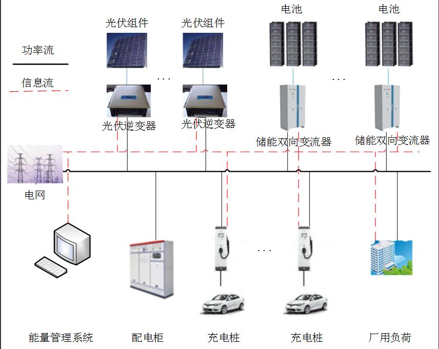
The composition of the photovoltaic storage and charging system in this article takes the second carport of the Minhang Industrial Zone Smart Energy Demonstration Project as an example. The photovoltaic storage and charging system mainly includes an energy management system, a photovoltaic system, a charging pile system, and an energy storage system. The system composition is shown in the figure.
1.1 Energy Management System
The energy management system is mainly responsible for data collection, display, and storage of photovoltaic, energy storage, charging piles, and incoming electricity meter equipment. At the same time, it coordinates and controls energy according to the requirements of the photovoltaic storage and charging system, thereby improving system reliability and economy.
1.2 Photovoltaic System
The photovoltaic system mainly consists of photovoltaic panels installed on the roof of the carport and four 35kW string photovoltaic inverters. The photovoltaic system is connected to the 400V busbar inside the station, and the photovoltaic output is prioritized to meet the load inside the station. If there is surplus output, it supplies power to the energy storage system.
1.3 Energy storage system
The energy storage system mainly consists of two sets of retired lithium iron phosphate batteries, each set consisting of a 35kW energy storage bidirectional converter and a 153.6kW · h battery cluster. The energy storage system is connected to the 400V bus in the station. When there is surplus photovoltaic output, the energy storage system absorbs the remaining output. When the photovoltaic output is insufficient to meet the load output, the energy storage system discharges to supplement the output. At night valley prices, energy storage systems purchase electricity from the grid until fully charged.
1.4 Charging Station System
The charging station system mainly consists of 6 AC single gun floor standing charging stations with a rated capacity of 7kW. The charging station system can charge small electric vehicles with DC motors and is also a part of the station's load composition. The charging station system mainly includes functions such as card swiping management, billing management, charging interface management, and security protection.
2. Working principle of photovoltaic energy storage system
Photovoltaic power generation: Photovoltaic cells generate direct current under sunlight. This process is the power input of the system.
Electricity conversion: DC electricity is converted into AC electricity through an inverter for use in the power grid or supply to AC equipment.
Energy storage: The remaining electrical energy can be stored in batteries or other energy storage devices for future use. This is the energy storage part of the system.
Energy management: The energy management controller of the system monitors energy demand, battery status, and other parameters, and allocates electrical energy as needed. It ensures that the system can provide continuous and reliable power supply under unpredictable solar energy supply conditions.
Grid Interconnection: If the system is interconnected with the grid, excess electricity can be sold to the grid, thereby achieving bidirectional current. This helps to improve the economy and sustainability of the system.
3. Structure of Optical Energy Storage and Charging Management System (EMS)
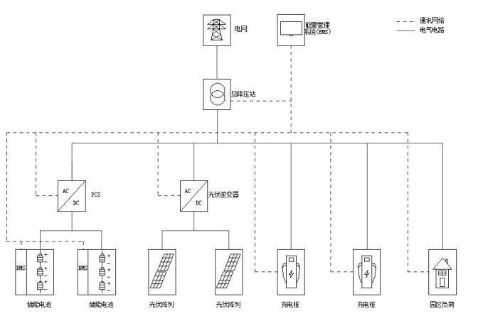
The photovoltaic storage and charging system is divided into three parts: photovoltaic power generation system, energy storage system, and charging pile system. The three systems are coupled through AC400V bus 49 and communicate with EMS via Ethernet, with EMS coordinating and controlling the operational strategies of each system. EMS can transmit monitoring data to remote monitoring systems and large screen display systems through the network. The system architecture of the photovoltaic charging system is shown in the following figure.
EMS is the core component of the optical storage and charging system, responsible for the underlying data acquisition, system network monitoring, energy management scheduling, and operational data analysis of the entire system. To ensure the stable operation of the optical storage and charging system, EMS adopts a two-level hierarchical control system, which is divided into local EMS and centralized control EMS. The structural diagram is shown in the following figure.
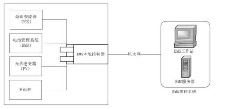
Local EMS can collect data from energy storage inverters (PCS), battery management systems (BMS), photovoltaic inverters, charging stations, and the power grid, and develop and operate different energy management strategies based on different usage scenarios such as peak and valley electricity prices, power rationing policies, and emergency needs. The local EMS controls the PCS to perform corresponding actions by sending active, reactive, and other control instructions to the PCS, and can also upload real-time operating status of the monitored optical storage and charging system, as well as various equipment status information within the system, to the centralized control EMS.
The centralized control EMS consists of EMS workstations and EMS servers. The main function of the EMS workstation is to monitor the real-time operation status of the optical storage and charging system, and to be responsible for developing the operation mode of the optical storage and charging system; The main function of the EMS server is to store the operational data of the optical storage and charging system, and provide services such as historical data query and data analysis. It is a prerequisite guarantee for formulating operational strategies based on big data analysis in the later stage.
4. Acrel-2000ES Energy Storage Cabinet Energy Management System
4.1 System Overview
Acrel-2000ES, an energy storage management system developed specifically for industrial and commercial energy storage cabinets and containers, is an energy storage EMS with comprehensive energy storage monitoring and management functions. It covers detailed information of energy storage system equipment (PCS, BMS, electricity meters, fire protection, air conditioning, etc.), and realizes functions such as data collection, data processing, data storage, data query and analysis, visual monitoring, alarm management, statistical reporting, etc. Support energy scheduling in applications, with control functions such as planning curves, peak shaving and valley filling, demand control, and backflow prevention.
4.2 System Architecture
Acrel-2000ES, The equipment inside the energy storage cabinet or container can be connected to the system through direct procurement, communication management, or serial server. The system structure is as follows:
4.3 System Functions
4.3.1 Real time monitoring
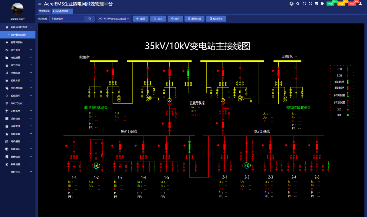
The system has a user-friendly human-machine interface that can display the operating status of the energy storage cabinet, monitor real-time PCS, BMS, and environmental parameter information such as electrical parameters, temperature, humidity, etc. Real time display of information related to faults, alarms, benefits, etc.
4.3.2 Equipment Monitoring
The system can monitor the operation status and mode of PCS, BMS, electricity meter, air conditioning, fire protection, dehumidifier and other equipment in real time.
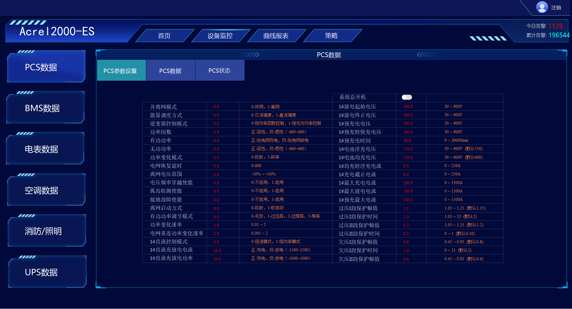
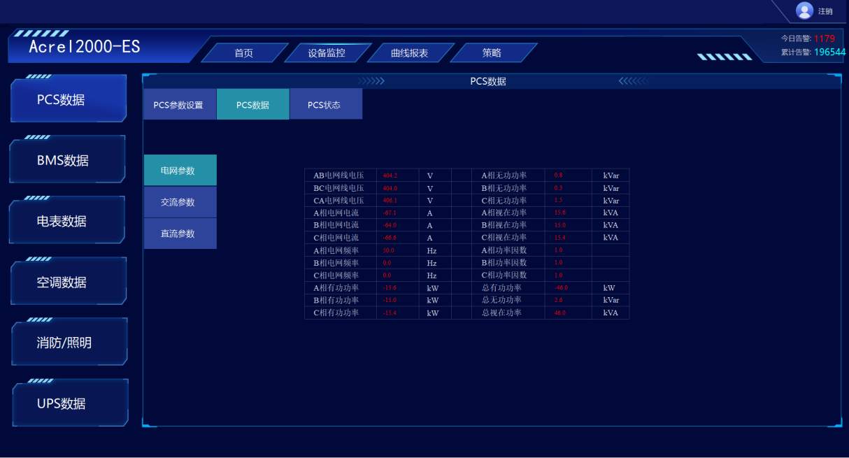
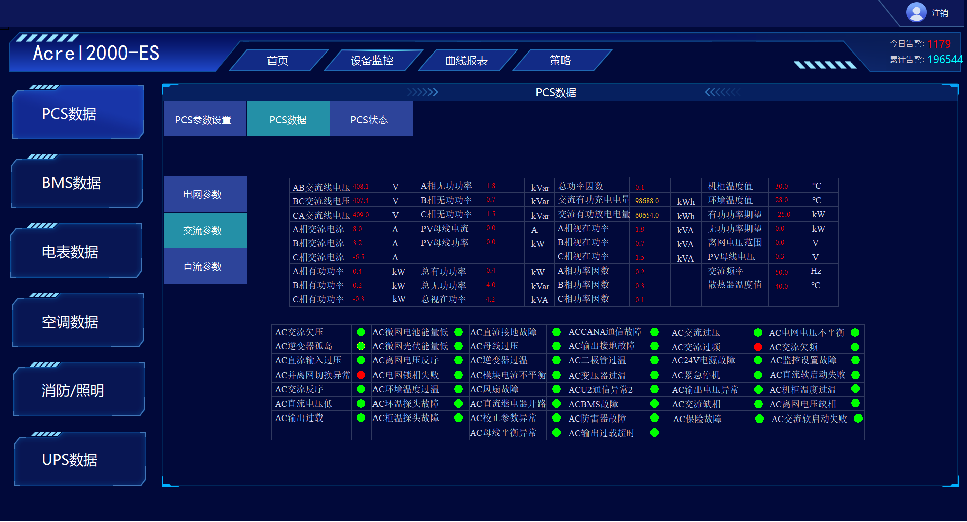
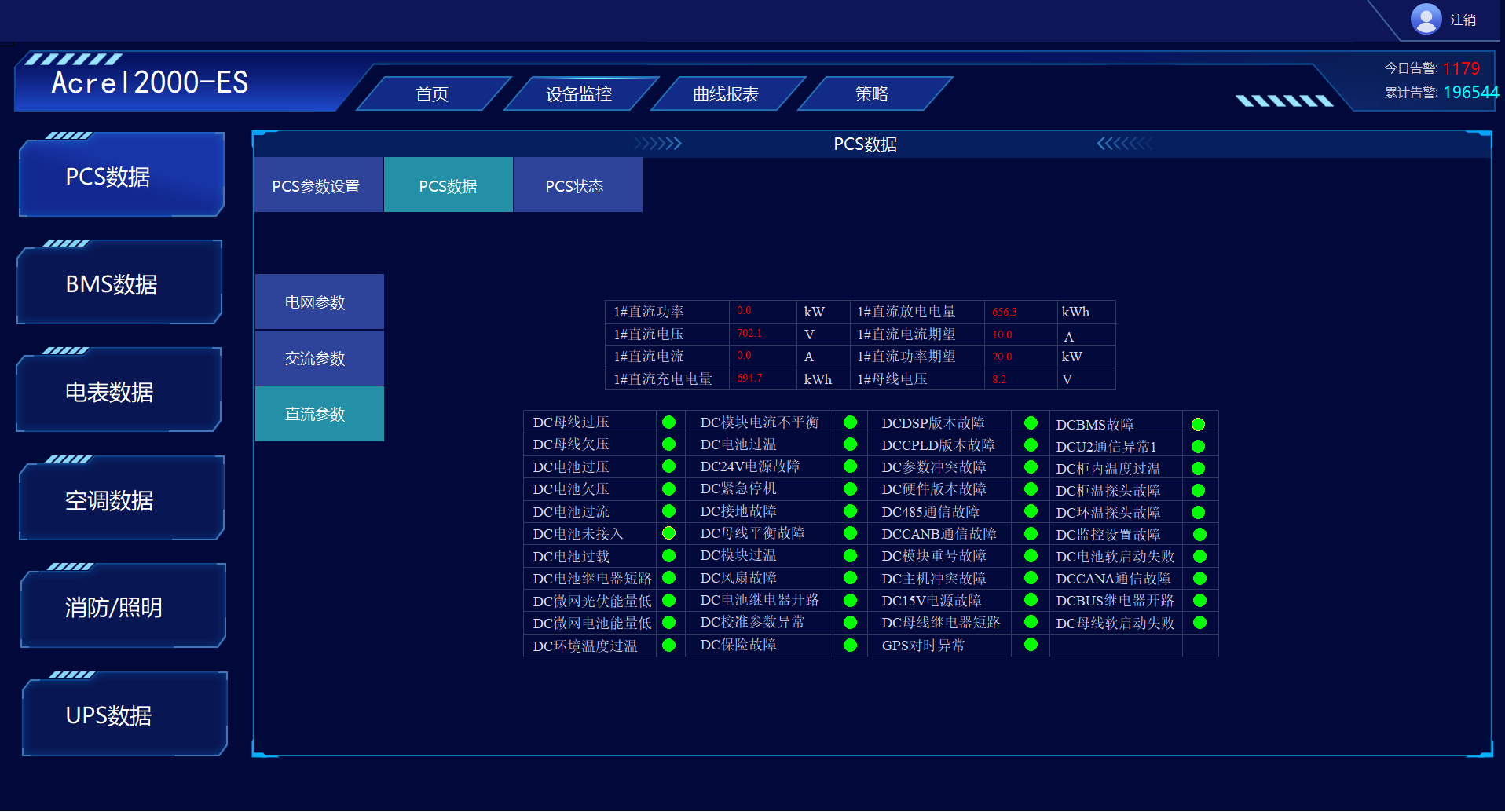
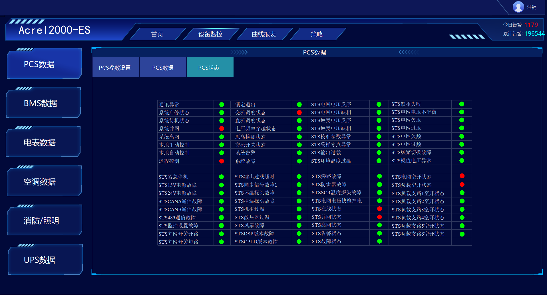
PCS monitoring: meet the parameter and limit settings of energy storage inverters; Operation mode setting; Realize the collection and display of voltage, current, power, and charging/discharging parameters on the AC/DC side of energy storage inverters; Implement monitoring of PCS communication status, start stop status, switch status, abnormal alarms, and other states.
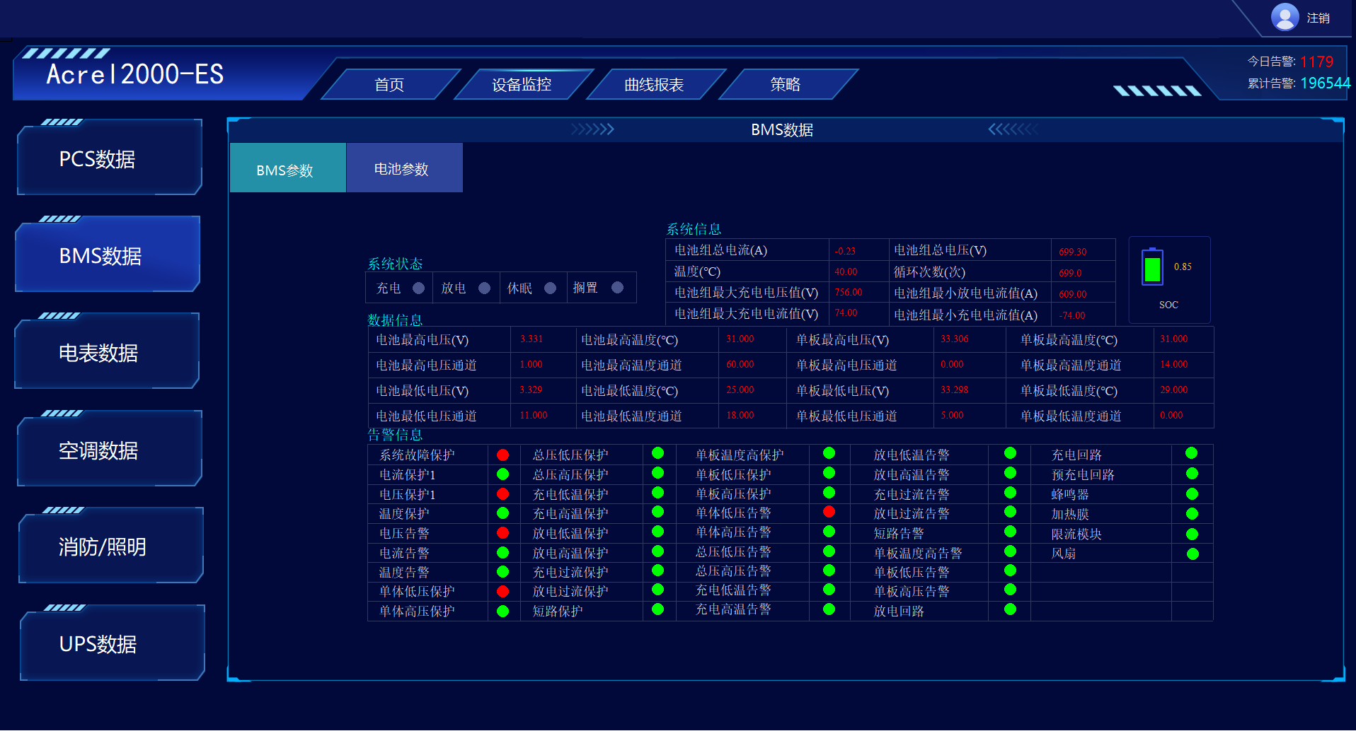
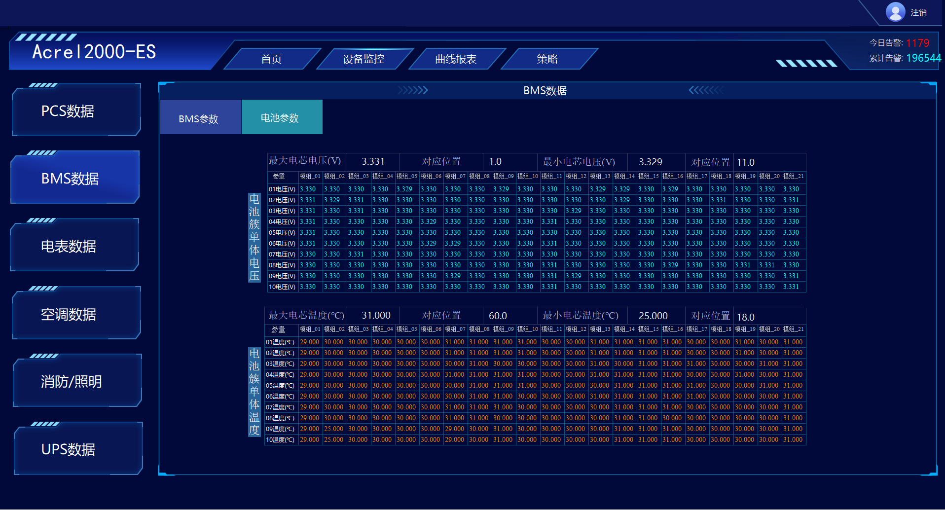
BMS monitoring: meets the parameter and limit settings of the battery management system; Monitor the temperature, voltage, and current of energy storage battery cells and clusters; Realize alarms for abnormal battery charging and discharging status, voltage, current, and temperature.
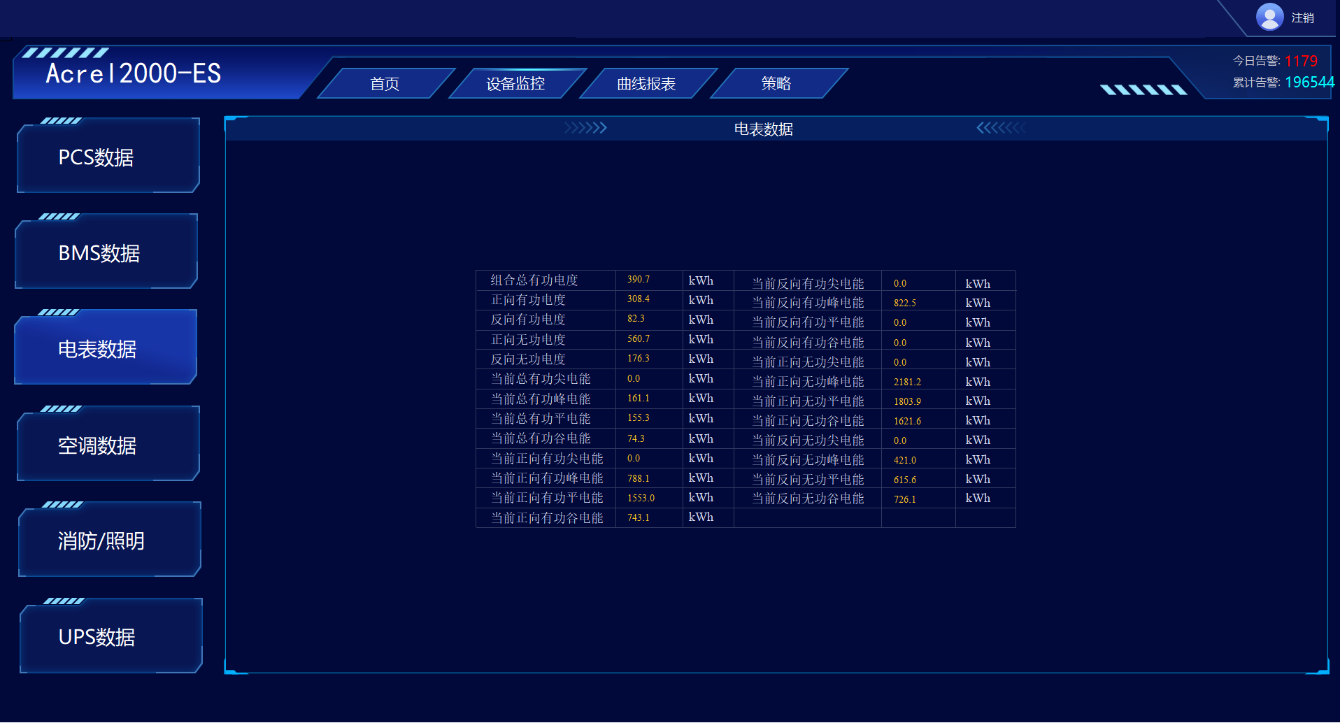
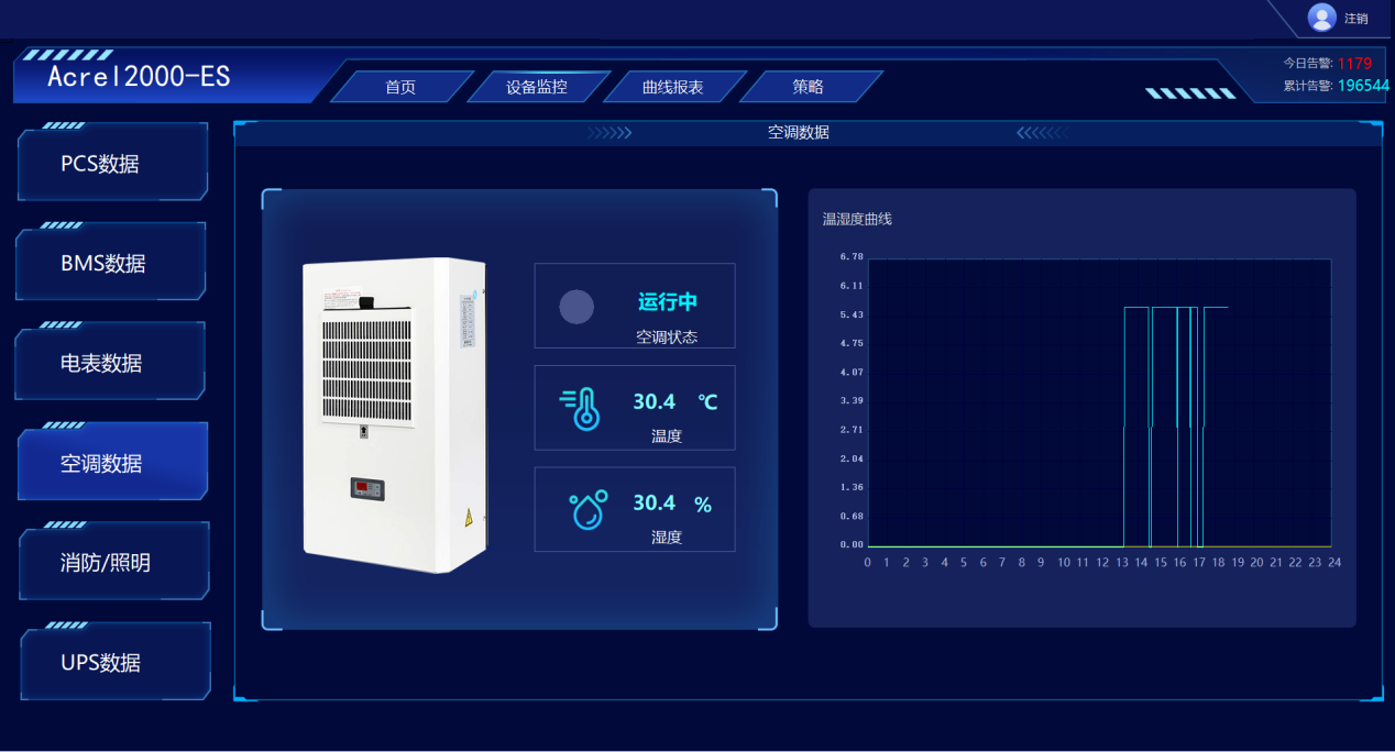
Air conditioning monitoring: To meet the monitoring of environmental temperature, the air conditioning temperature can be linked and adjusted according to the set threshold, and the operating status and temperature and humidity data of the air conditioning can be monitored in real time, displayed in the form of curves.
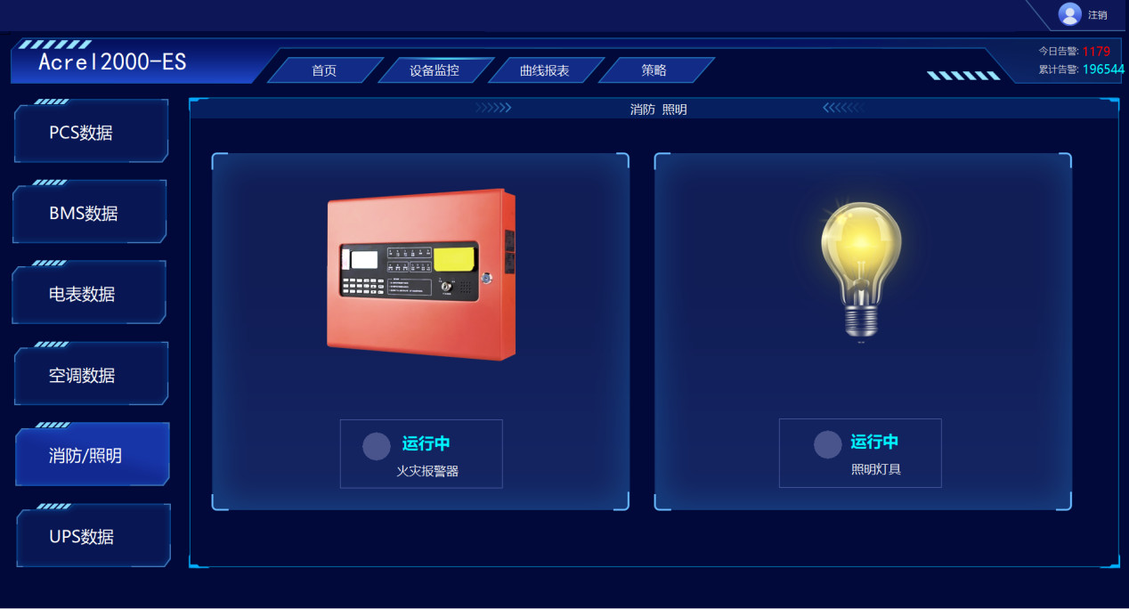
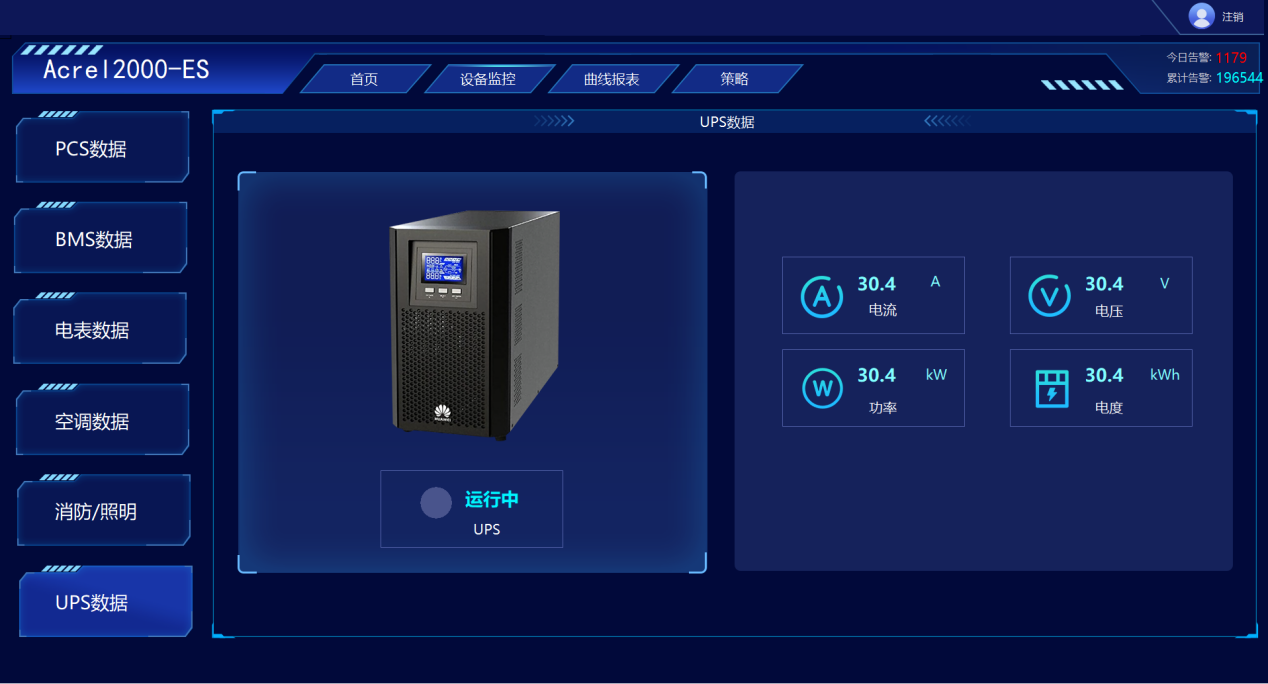
UPS monitoring: meet the monitoring of UPS operation status and related electrical parameters.
4.3.3 Curve Report
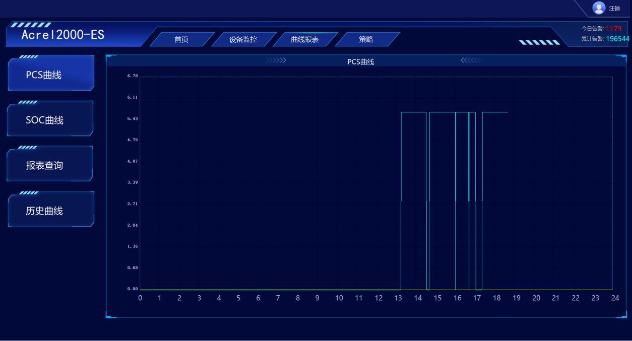
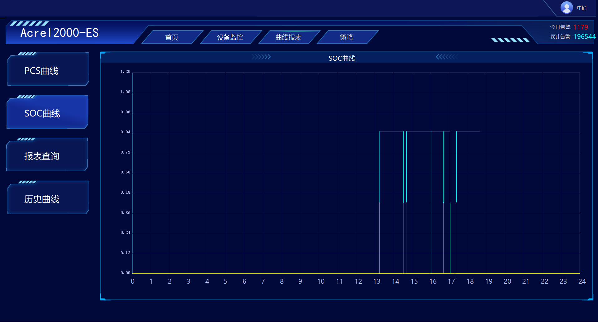
The system is capable of querying and displaying PCS charging and discharging power curves, SOC conversion curves, as well as historical curves such as voltage, current, and temperature.
 4.3.4 Strategy Configuration
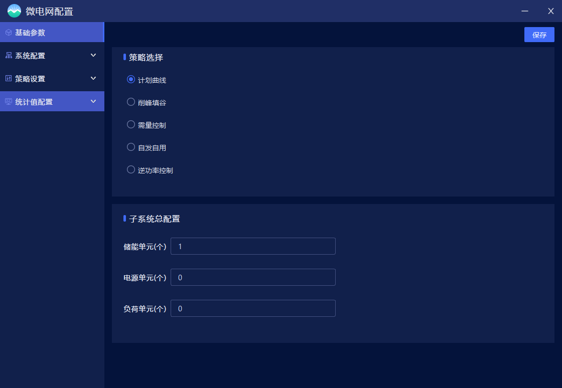
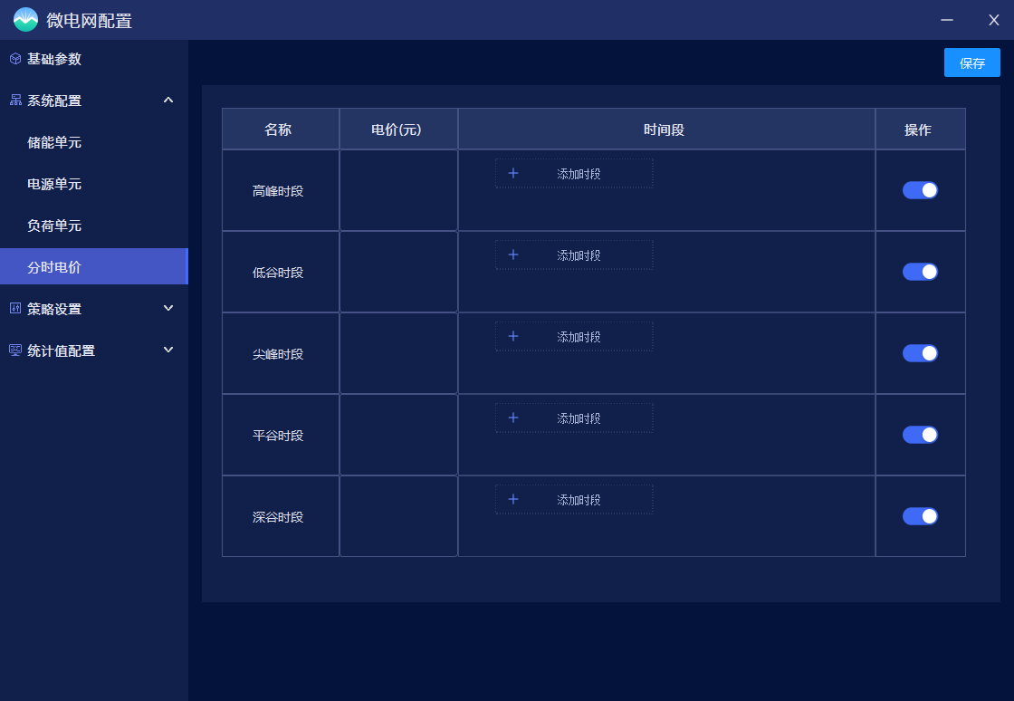
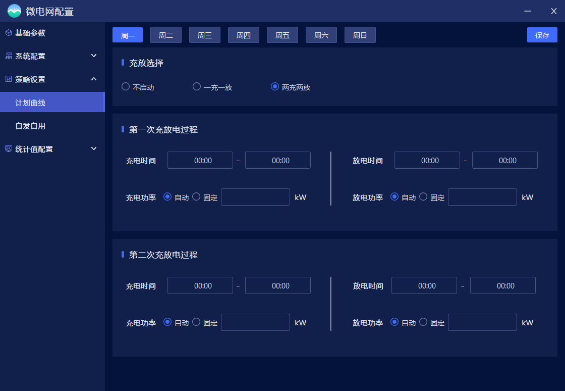
Satisfy the configuration of energy storage system equipment parameters, the setting of electricity price parameters and time periods, and the selection of control strategies. The currently supported control strategies include planning curves, peak shaving and valley filling, demand control, etc.
 4.3.5 Real time alarm
The energy storage management system has real-time alarm function, which can issue alarms for events such as energy storage charging and discharging exceeding limits, temperature exceeding limits, equipment failure or communication failure.
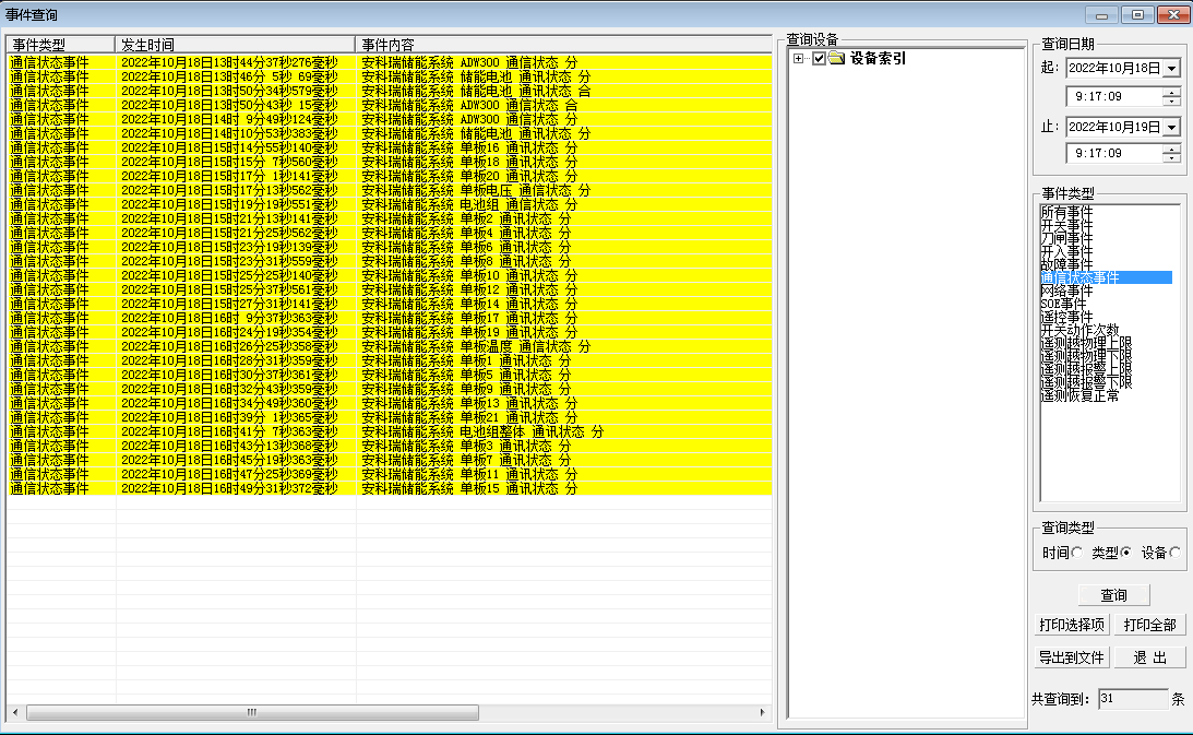
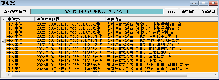 4.3.6 Event Query Statistics
The energy storage management system can store and manage event records such as remote signal displacement, temperature and humidity, and voltage exceeding limits, making it convenient for users to trace the history of system events and alarms, query statistics, and analyze accidents.
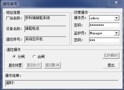
 4.3.7 Remote control operation
The PCS, fans, dehumidifiers, air conditioning controllers, lighting and other equipment can be controlled through the red buttons below each device. However, when the devices are not communicating, the control buttons will display an invalid status.
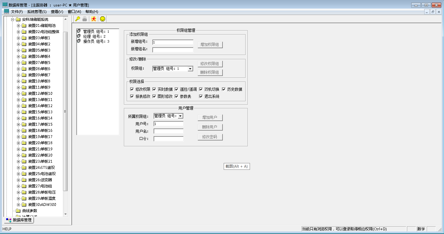
4.3.8 User Permission Management
The energy storage management system has set up user permission management functions to ensure the safe and stable operation of the system. User permission management can prevent unauthorized operations (such as remote control operations, database modifications, etc.). It is possible to define login names, passwords, and operational permissions for users of different levels, providing reliable security for system operation, maintenance, and management.
This article proposes an energy management strategy based on the principle that the second carport photovoltaic storage and charging system of the Minhang Industrial Zone Smart Energy Demonstration Project is self operated and not connected to the grid. The strategy involves consuming photovoltaic output during the day, storing energy to supplement the photovoltaic output when it is less than the load, and storing energy to consume the remaining photovoltaic output when it is greater than the load. At night electricity prices are flat, energy storage continues to supply power to the load, and if there is insufficient electricity, it is purchased from the grid. At night valley prices, energy storage systems purchase electricity from the grid until fully charged. This strategy has been running for a long time, and through data analysis, it has met the operational requirements of the light storage and charging system.