-
Phone
13813156012
-
Address
Zhenxing North Road, Zhenwu Town, Jiangdu District, Yangzhou City, Jiangsu Province
Product Categories
- Density meter
- melt indexer
- Elasticity meter
- Digital tensile machine
- compression set
- mould
- Thickness gauge
- Low temperature brittleness tester
- Computer tensile machine
- Planing machine
- Plasticity testing machine
- Notch prototype
- Fatigue cracking testing machine
- Cutting knife
- Insulation resistance meter
- Compression stress relaxation instrument
- Mooney Viscometer
- Dumbbell prototype
- Roller Wear Machine
- Akron abrasion machine
- Hot deformation Vicat
- Rubber cutting machine
- Special film paper for vulcanizing tester Menni
- Double head slicer
- impact testing machine
- Tensile testing machine
- Hardness tester
- Vulcanizer, Rotorless Vulcanizer, Rheometer, Rotorless Rheometer
- Aging chamber, ozone aging chamber
Yangzhou Zhengyi Experimental Machinery Co., Ltd
Rubber tensile testing machine
NegotiableUpdate on 04/08
- Model
- Nature of the Manufacturer
- Producers
- Product Category
- Place of Origin
Overview
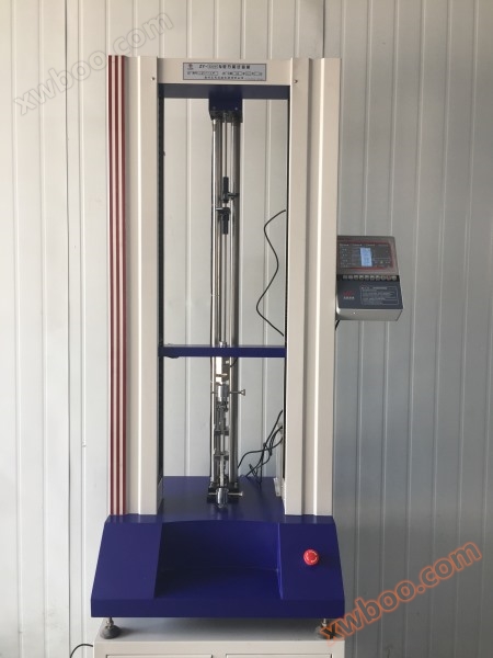
Rubber tensile testing machine
Product Details
ZY-5000N Rubber Electronic Tensile Machine
The ZY series digital electronic tensile testing machine is an instrument used to test the mechanical properties of materials, such as tensile strength, peeling, tearing, and H-extraction. Widely used in industries such as rubber, plastic, textile, chemical, steel wire, rubber hose, wire and cable, plastic, pipe, etc., it is a high-precision, economical and practical instrument.
The tensile machine consists of a host, a speed control system, data acquisition and processing, sensors, and electrical interlocking. The host includes the body, transmission mechanism, and measurement system. Data processing is handled by a microcomputer processor. This machine uses a stepper speed controller to change the stretching speed, and the speed value is directly read out. The motor drives the lower gripper (fixture) through V-belt worm screw transmission, thereby achieving the tensile change of the sample. The host head is equipped with a tension sensor, with its upper end connected to the connecting plate of the top crossbeam of the host and its lower end connected to the upper clamp. The sensor is only subjected to vertical tension and is not affected by torsion or direction finding force to ensure force measurement accuracy. The sample is clamped between the upper and lower clamps, and during the test process, the force on the sample is converted into an electrical signal by the force sensor and input into the microcomputer acquisition and control system. After the experiment is completed, it will be automatically processed, calculated, and the results will be displayed.
This touch LCD measurement and control system adopts 32-bit ARM technology and DSP high-performance processor control technology. The display part adopts a 7-inch 65K color ultra clear touch screen with a resolution of 1024 * 768. The ultra-high performance configuration greatly improves the software functions and user experience. The software includes startup animation, main screen display, large curve display, unit setting, selection and result calculation display of multiple test standards, device status display, hardware parameter setting, device calibration, PID parameter setting, customized parameter editing, sample scheme editing, sample size editing, visual printing and other functions. The micro printer supports multiple models to choose from, and the motor control supports free switching of servo, stepper, frequency conversion, DC and other control methods (no need to replace the system at the factory, standard functions).
This experimental measurement and control system is a high-performance measurement and control instrument designed specifically for electronic testing machines, which integrates measurement and control. It can perform tests such as tension, compression, bending, shear, tearing, and peeling. The software can complete the calculation and real-time display of parameters such as maximum force, maximum deformation, tensile strength, elongation at break, total elongation at maximum force, yield point elongation, post fracture elongation, upper and lower yield strengths, elastic modulus, yield point force, elongation at break, yield point elongation, tensile strength at break, tensile stress at yield point, tensile stress at constant tension, and elongation at constant tension (according to the user specified force level). Among them, the horizontal values of tensile strength and tensile strength can be input into the relevant positions of the software on the sample parameter interface according to the actual requirements of the customer's use. The parameters that can be calculated also include compressive strength, upper and lower compressive yield strength, compressive modulus of elasticity, flexural strength, flexural modulus of elasticity, average bending force, average peel force, peel strength, maximum peel force, minimum peel force, tear strength, average shear force, shear strength, shear modulus and other mechanical and physical properties related parameters.
Introduction to Main Interface Functions
Real time display of data
The system can display 4 channels of data simultaneously, namely force value, displacement, deformation, and velocity. After the touch screen is powered on, the data is automatically collected and the display is refreshed. Force resolution of 1/250000, accuracy of 0.2% or above, range of 1-9999999KN arbitrary; The resolution of displacement sensors and deformation sensors can reach up to 1um, with a response frequency of 40kHz and a range of 0-10000mm that can be set arbitrarily. The precision instrument system has no errors and is a 4-phase decoding type;
Real time switching of units
Switching of force units (N, KN, g, kg, gf, kgf, Ib, Ibf, oz, ozf), and switching of deformation and displacement units (mm, cm, m, in). The unit switching settings are completed on the "Sample Parameters" page. After the switching is completed, the numerical and result display data on the main interface are automatically converted.
Calculation of experimental results
According to different calculation methods, the display content of the test result list automatically switches. After selecting the calculation method, the next time the power is turned on, the last selected calculation method will be automatically defaulted for the test.
Real time display of curves
The system provides two ways to display the main interface: a convenient small curve interface and a "single graph" large curve interface. In standby mode, click "single graph" to display the large curve interface, and click "back to home page" to automatically switch back to the monitoring main page. The coordinate axis range of the two curves can be freely set according to needs.
Test control button
The touch screen system provides a set of touch screen control buttons for experimental control, which can help improve the user experience.
After the device is ready, it is allowed to start running the test (if there is an abnormal prompt on the device, clicking "Run" will sound an alarm for abnormal operation, and the user can follow the prompts to guide the completion of the operation);
[Stop] Stop the test or stop the control command for the movement of the crossbeam;
Reset all sensor data (resetting is invalid when the crossbeam is moving, the test is running, or the force sensor is abnormal, and the system will sound an alarm for abnormal operation. Users can follow the prompts to complete the reset operation);
【 UP Upward 】 Manually control the upward movement of the crossbeam in a progressive manner. With each click, the movement speed will continuously increase in the same direction. The movement speed can be modified as needed in the "Custom Parameters" section (when the crossbeam is moving in reverse, during experimental operation, during upper limit protection, or when the force sensor is abnormal, the upward movement is invalid, and the system will sound an alarm indicating abnormal operation. Users can follow the prompts to complete the upward movement operation);
Manually control the downward movement of the crossbeam gradually. With each click, the movement speed will continuously increase in the same direction. The movement speed can be modified as needed in the "Custom Parameters" (when the crossbeam is moving in reverse, during experimental operation, under lower limit protection, or when the force sensor is abnormal, the system will sound an alarm for abnormal operation. Users can follow the prompts to complete the downward operation);
When in standby mode, manual unloading control is used to automatically release the applied load when there is an abnormal stop or sensor force failure during the test. After the load returns to zero, the crossbeam automatically stops and can be manually stopped and unloaded midway.
Test status and abnormal information
【▲】 Horizontal beam upward movement indicator (the upward movement LED indicator light on the keypad is on)
【▼ 】 Horizontal beam downward indication (the downward LED indicator light on the keypad is on)
[| |] In standby mode, the crossbeam stops moving (the LED indicator on the keypad does not light up)
Upper limit protection: The system restricts the horizontal beam from moving up, moving down, or manually releasing the upper limit protection.
[Lower limit to] Lower limit protection, the system restricts the horizontal beam from moving down, the horizontal beam from moving up, or manually releases the lower limit protection.
After the experiment is completed, the system will execute automatic return according to the protocol settings. It will automatically stop when returning to the position origin or manually stop the return. During the automatic return process, commands such as running, resetting, up and down movement, unloading, and parameter setting will be prohibited (if there is any abnormal operation, the system will sound an alarm for abnormal operation, and the user can follow the prompts to complete the relevant operations).
[Force Over Range] Force Over Range Protection: In case of sensor failure or force over range, the system restricts the up and down movement of the crossbeam. After manually troubleshooting or clicking [Force Value Return to Zero] to release the abnormal load, the alarm will be automatically cancelled.
[Displacement Over Range] Displacement over range protection, the system restricts the up and down movement of the crossbeam. After confirming that there has been no collision, click [Reset] to cancel the alarm. After the abnormality is resolved, the alarm will be automatically canceled.
Deformation Over Range Protection: The system restricts the up and down movement of the crossbeam. After confirming that there has been no collision, click [Reset] to cancel the alarm. Once the abnormality is resolved, the alarm will be automatically cancelled.
[Preloading] After the experiment begins, the system will execute preloading control according to the plan before the experiment starts. After preloading is completed, it will automatically enter the running state, and the alarm information will be automatically released. During preloading, the system prohibits abnormal operations (if there are abnormal operations, the system will sound an alarm for abnormal operations, and the user can follow the prompts to complete the relevant operations).
Main specification and technical parameter
Execution standard: GB/T16491-2008
Accuracy: within ± 1% of the displayed value
Power supply:~220 ± 10% V/50 Hz;
Humidity: 30% -85%;
Instrument fuse: 1A
Stretching speed: 0~500mm/min
Maximum travel of gripper: 800mm
Jaw automatic (manual) return function;
Multiple limit switches are available, and the force overload protection function can be set;
Multiple testing and control methods including constant speed, constant elongation, constant load, constant speed, and positioning displacement.
The speed control of this instrument only requires positioning and displacement direction to automatically control the operating speed.
Fault self check and prompt function: memory, AD chip, memory chip, CPU program, upper limit protection, lower limit protection and other faults, force sensor not connected or overloaded, force sensor not calibrated.
Test data correction function.


