-
E-mail
3008232806@qq.com
-
Phone
18701808662
-
Address
253 Yulu Road, Jiading District, Shanghai
Product Categories
Ankerui Electric Co., Ltd
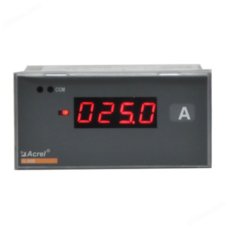
Embedded DC ammeter with 91 * 44 openings
NegotiableUpdate on 01/08
- Model
- Nature of the Manufacturer
- Producers
- Product Category
- Place of Origin
Overview
Embedded DC ammeter with 91 * 44 $r $n opening. This series of instruments can measure DC current, DC voltage, various types of thermocouples, thermal resistors, and resistance sensors. It comes with a DC24V power output and can directly supply power to external two-wire transformers. The instrument has multiple optional functions: RS485 interface, analog output, switch input, relay alarm output, etc.
Product Details
The PZ96B series single-phase meter adopts AC sampling technology and can directly or indirectly measure voltage, current, etc. in single-phase power grids. It can be used for local display and can also be connected to industrial control equipment to form a measurement and control system.
The instrument may have an RS-485 communication interface and use Modbus RTU protocol; Can be equipped with analog output, relay alarm output, and switch input/output. According to different requirements, parameters such as transformation ratio, alarm, and communication can be set and controlled through the dashboard buttons.
1、 Technical parameters

2、 External dimensions


3、 Wiring method

4、 Precautions
5.1 Voltage Input
The input voltage should not exceed 120% of the rated input voltage of the product, otherwise PT should be considered;
A 1A fuse must be installed at the voltage input terminal;
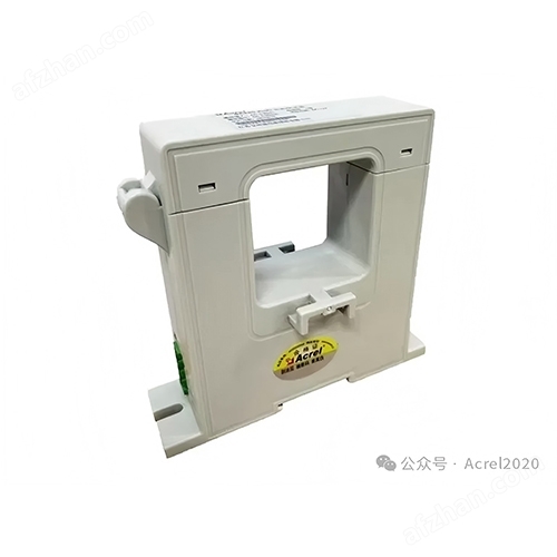
5.2 Current input
The current input must be connected using an external CT.
Ensure that the input current and voltage phase sequence are consistent when wiring, otherwise display values and symbols may be incorrect; At the same time, ensure that the current input and output lines are connected correctly (with the marked * terminal connected to the input line);
If other instruments are connected to the CT used, the wiring should be connected in series;
When installing wiring, it is recommended to use a wiring harness instead of directly connecting to a CT for ease of disassembly and assembly;
Before removing the current input connection of the product, the CT primary circuit must be cut off or the secondary circuit must be short circuited.
DC current input should use an external shunt or DC transmitter
5.3 Communication Wiring
This instrument provides asynchronous half duplex RS485 communication interface, using MODBUS-RTU protocol, and various data information can be transmitted on the communication line. In theory, up to 128 instruments can be connected simultaneously on a single line, and each instrument can set its communication address (Addr), and the communication rate (buad) can also be selected through settings.
It is recommended to use three core shielded wires with a diameter of not less than 0.5mm2 for communication connections, connected to A, B, and COM respectively. The shielding layer should be grounded. When wiring, the communication wires should be kept away from strong electrical cables or other strong electric field environments.
Suggest adding a matching resistor between A and B of the end instrument, with a resistance range of 120 Ω to 10k Ω.
Embedded DC ammeter with 91 * 44 openings
Embedded DC ammeter with 91 * 44 openings
Similar Product Recommend