-
E-mail
441955402@qq.com
-
Phone
13175671188
-
Address
Room 910, 9th Floor, Building 2, No. 64 Tiancheng Road, Shangcheng District, Hangzhou City, Zhejiang Province
Product Categories
Hangzhou Hangrui Electric Power Automation Co., Ltd


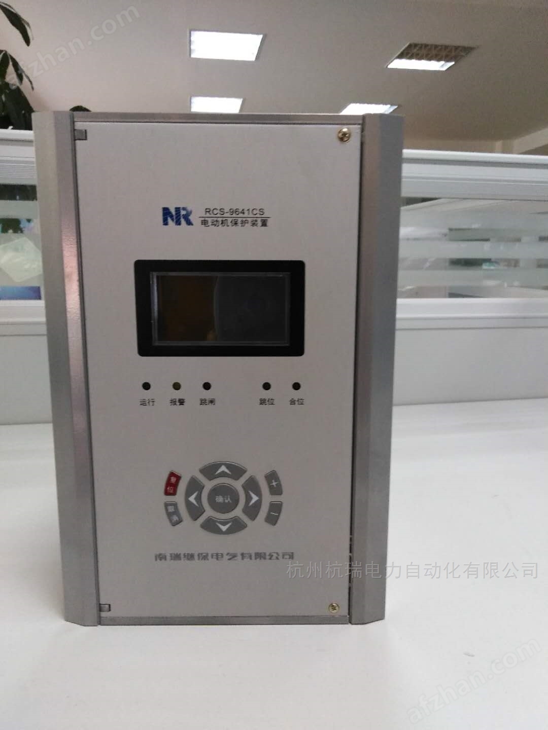
Nanrui Jibao RCS9611CS microcomputer protection device
NegotiableUpdate on 02/13
- Model
- Nature of the Manufacturer
- Producers
- Product Category
- Place of Origin
Overview
The Nanrui Jibao RCS9611CS microcomputer protection device $r $nRCS-9000CS series protection measurement and control device integrates protection and remote control functions into one device, which is called the "four in one" protection (protection, telemetry, remote control, remote communication). Targeting different medium and low voltage protection measurement and control objects in enterprise power systems
Product Details
Nanrui Jibao RCS9611CS microcomputer protection device
RCS-9611CS Line Protection Measurement and Control Device
RCS-9611CS is suitable for non directly grounded systems or low resistance grounded systems with voltage levels below 110kV
Line protection and measurement and control devices.
Protection configuration:
1) Three stage overcurrent protection that can withstand overvoltage and directional locking;
2) Three stage zero sequence overcurrent protection;
3) Overcurrent acceleration protection and zero sequence acceleration protection (zero sequence current can be self generated or externally added);
4) Overload function (alarm or trip);
5) Low cycle load reduction function;
6) Two stage low voltage protection;
7) Overvoltage protection for a section of busbar;
8) A section of zero sequence overvoltage protection;
9) A period of high week protection;
10) Three phase primary reclosing;
11) Low current grounding line selection function (must use external zero sequence current);
12) Independent operating circuit;
13) Export configuration function.
Measurement and control function:
1) 16 custom remote signaling inputs;
2) A set of remote control circuit breakers for opening/closing (up to three sets of remote control can be provided as an optional option);
3) Iam, Icm, I0, UA, UB, UC, UAB, UBC, UCA, U0, F, P, Q, COS ф, a total of 14 remote sensors
Measurement;
4) Event SOE records, etc.
Nanrui Jibao RCS9611CS microcomputer protection device
6.1 Device tuning
The buttons' ▲ 'and' ▼ 'are used to scroll and select the fixed value to be modified, while the buttons' ◄' and '►' are used to move the cursor
Move to the location to be modified, '+' and '-' are used to modify data, press' Cancel 'to abandon the modification and return, press
The 'confirm' button completes the set value setting and returns.
Note: No password is required to view the fixed value. If you want to modify the fixed value, you need to enter a password. If the password is incorrect, there will be a prompt message.
6.2 Status Display
This menu is mainly used to display the real-time sampling values and switch status of the current and voltage of the protection device, which comprehensively reflects the
The operating status of the device. Only when the displayed values of these quantities are consistent with the actual operating conditions, can the protection work correctly. suggestion
Check these quantities during operation.
Menu Selection
1. Device tuning
2. Status display
3. Report display
4. Report printing
5. On site setup
6. Device debugging
7. Version information
8. Factory settings
0. Exit
Device tuning
1. Protection setting
2. System settings
3. Communication parameters
4. Auxiliary parameters
5. Soft pressing plate modification
0. Exit
status display
1. Sample value display
2. Phase angle display
3. Remote measurement display
4. Switching status
5. Soft pressing plate status
0. Exit
Report printing
1. Parameter printing
2. Fixed value printing
3. Trip report
4. Operation report
5. Self inspection report
6. Remote signaling report
7. Status printing
8. Waveform printing
0. Exit
The report shows
1. Trip report
2. Operation report
3. Remote signaling report
4. Operation report
5. Self inspection report
0. Exit
Version Information
1. Protect the program
2. Communication program
0. Exit
on-site setup
1. Time setting
2. Report clearance
3. Reset the electrical degree to zero
0. Exit
Device debugging
1. Remote signaling sequence test
2. Remote signaling point selection test
3. Export transmission test
4. Telemetry signal test
5. Start the wave recording test
0. Exit
in-plant settings
1. Manual adjustment of accuracy
2. Automatic precision adjustment
3. Device initialization
0. Exit
Similar Product Recommend